
Resonant cavity based on non-periodic sub-wavelength grating and distributed bragg reflector

A Bragg reflector and subwavelength grating technology, which is applied in the field of resonators, can solve the problems such as the inability to control the variation of the standing wave field width, and limit the application range of the resonator, and achieve the effects of excellent structure, high integration and stable performance.

Active Publication Date: 2018-02-16
BEIJING UNIV OF POSTS & TELECOMM
View PDF4 Cites 0 Cited by
  • Summary
  • Abstract
  • Description
  • Claims
  • Application Information

AI Technical Summary

Problems solved by technology

[0004] Since the width of the stable standing wave field that can be formed in each resonator is fixed and is not much different from the width of the resonator, the width of the standing wave field cannot be controlled to change, which limits the application range of the resonator in optical communication systems

Method used


Image

  • Resonant cavity based on non-periodic sub-wavelength grating and distributed bragg reflector
  • Resonant cavity based on non-periodic sub-wavelength grating and distributed bragg reflector
  • Resonant cavity based on non-periodic sub-wavelength grating and distributed bragg reflector

Examples


Embodiment Construction

[0018] The specific implementation manners of the present invention will be further described in detail below in conjunction with the accompanying drawings and embodiments. The following examples are used to illustrate the present invention, but are not intended to limit the scope of the present invention.

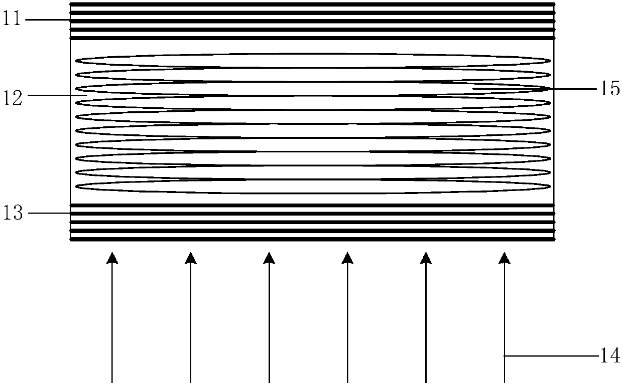
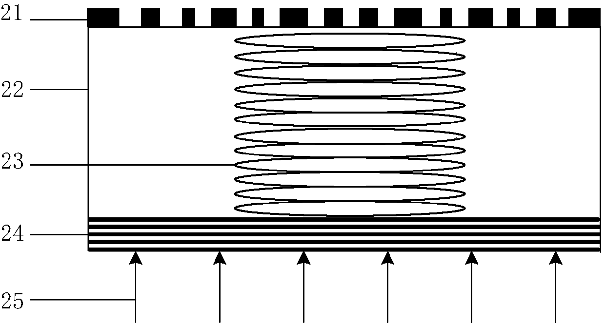
[0019] Such as figure 2 As shown, an embodiment of the present invention provides a resonant cavity, the resonant cavity has a cavity structure of two mirrors, and the two mirrors are respectively an aperiodic sub-wavelength grating reflector and a distributed Bragg reflector (Distributed BraggReflector, DBR ), the two mirrors are placed in parallel and facing each other; the one cavity is a resonant cavity formed by the two mirrors.

[0020] figure 2 Among them, the structure of the resonant cavity from bottom to top is: distributed Bragg reflector 24, resonant cavity 22, non-periodic sub-wavelength grating reflector 21, forming a two-mirror-one-cavity structure. Bot...


PUM

PropertyMeasurementUnit
Grating periodaaaaaaaaaa
Heightaaaaaaaaaa

Abstract

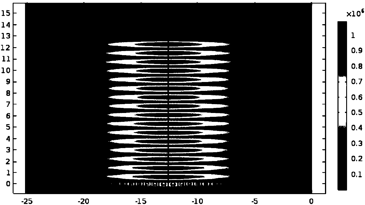
The present invention relates to the field of semiconductor photoelectronic device, and provides a resonant cavity based on a non-periodic sub-wavelength grating and a distributed bragg reflector (DBR). The resonant cavity based on a non-periodic sub-wavelength grating and a DBR has a feature of controlling distribution of a light standing wave field in the resonant cavity. The structure of the resonant cavity comprises from top to bottom: a DBR, a resonant cavity and a non-periodic sub-wavelength grating reflector. A planar incident light reaches the non-periodic sub-wavelength grating reflector through the resonant cavity to realize oblique reflection deflect towards the center of the resonant cavity, and the oblique reflection is subjected to multiple oscillation and coupling in the resonant cavity to form a stable standing wave field with light field energy concentrated on the middle portion of the resonant cavity, wherein the width of the standing wave field is determined by a structure of the non-periodic sub-wavelength grating, and therefore the structure of the non-periodic sub-wavelength grating is changed to achieve control of the width of the standing wave field in the resonant cavity. The problem is solved that a traditional resonant cavity cannot control the width of the standing wave field, and the resonant cavity based on the non-periodic sub-wavelength grating and the distributed bragg reflector can be widely applicable to the optical communication and optical system fields.

Description

technical field [0001] The invention relates to the field of semiconductor optoelectronic devices, more specifically, to a resonant cavity based on aperiodic sub-wavelength gratings and distributed Bragg reflectors. Background technique [0002] With the rapid development of optical communication systems, semiconductor optoelectronic devices have been widely used. In order to study optical communication systems with higher speed and larger capacity, researchers are required to design semiconductor optoelectronic devices with higher integration, better structure and more stable performance. [0003] Resonant cavity is an important cavity structure in semiconductor optoelectronic devices, which is widely used in lasers and photodetectors. Among them, the Fabry-Perot cavity (F-P cavity) is a typical cavity. The F-P cavity is also called a plane-parallel cavity. It is composed of two parallel plane mirrors (the radius of curvature of the two mirrors is infinite). A light paral...

Claims


Application Information

Patent Timeline
IPC IPC(8): G02B27/00H01S3/081
Inventor 段晓峰张帅李宫清黄永清任晓敏刘凯蔡世伟
Owner BEIJING UNIV OF POSTS & TELECOMM
Learn More