
Tiltable fold mirror for optical imaging system

An optical imaging system and mirror technology, applied in the field of folding mirrors, can solve the problems of high actuation force construction space, high energy consumption of image stabilization systems, etc.

Pending Publication Date: 2021-10-29
奥普托图尼瑞士股份公司
View PDF6 Cites 0 Cited by
  • Summary
  • Abstract
  • Description
  • Claims
  • Application Information

AI Technical Summary

Problems solved by technology

[0008] However, for actuation, the entire prism must be tilted, which requires a high actuation force and a large build space for the tiltable prism
This in turn leads to higher energy consumption of the image stabilization system

Method used


Image

  • Tiltable fold mirror for optical imaging system
  • Tiltable fold mirror for optical imaging system
  • Tiltable fold mirror for optical imaging system

Examples


Embodiment Construction

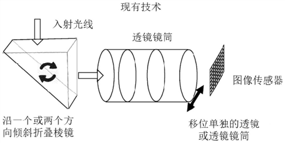
[0171] figure 1 An imaging system common in the prior art is shown. The imaging system includes an image sensor, a lens system (included in a rigid lens barrel), and a folded prism.

[0172] Such optical imaging systems are often included in compact handheld devices, such as mobile phones, mobile computers with cameras, where the space for components is usually very limited and often requires folding of the optical path by one or more folding prisms.

[0173] This is achieved by moving (as indicated by the solid black arrows) selected components of the imaging system such that even if the image sensor is moved, for example due to shaking of the person holding the imaging system, the incident light rays will hit the same location on the image sensor Optical image stabilization in such systems.

[0174] In this case, to achieve image stabilization, either the folded prism is tilted, or the lens barrel with the lens system is moved transversely to the optical path (indicated by...


PUM


Abstract

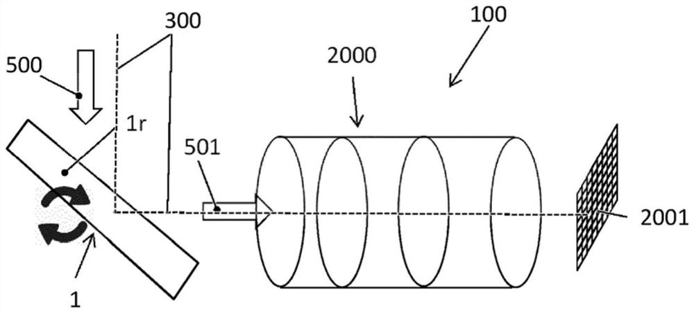
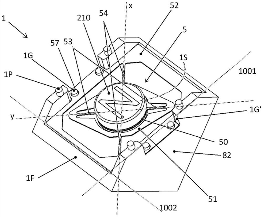
The invention relates to a tiltable mirror (1) for optical image stabilization in an optical imaging system (100), the tiltable mirror (1) comprising a rigid mirror substrate (1S) with a planar reflective layer (1R) on a front side of the mirror substrate (1S) for reflecting incident light (500) in an optical imaging system (100); a mirror frame (1F), wherein the mirror substrate (1S) is arranged tiltably in the mirror frame (1F); an actuator (2) for tilting the mirror substrate (1S) around a primary (x) and a secondary (y) tilt axis with respect to the mirror frame (1F). The invention further relates to an optical imaging system comprising a tiltable mirror (1) according to the invention.

Description

technical field [0001] The invention relates to a tiltable and adjustable folding mirror for an optical imaging system for optical image stabilization, and an optical imaging system comprising the mirror. Background technique [0002] An optical imaging system includes an image sensor, a lens system (eg included in a rigid lens barrel), and a folded prism. [0003] Such optical imaging systems are often included in compact handheld devices, such as mobile phones, mobile computers with cameras, where the space for components is usually very limited and often requires folding of the optical path by one or more folding prisms. [0004] By actively or passively moving (as indicated by the solid black arrows) selected components of the imaging system such that even if the image sensor is moved, for example due to shaking of the person holding the imaging system, the incident light will hit the same location on the image sensor , to achieve optical image stabilization in such sys...

Claims


Application Information

Patent Timeline
IPC IPC(8): G02B7/182G02B7/198G02B27/64H04N5/232G02B26/08G03B30/00
CPCG02B7/182G02B27/64G02B26/0816G02B26/085H04N23/55H04N23/685G02B7/1821H04N23/54
Inventor 斯蒂芬·斯莫尔卡迈克尔·布勒桑沽·别尔恩约翰内斯·哈斯
Owner 奥普托图尼瑞士股份公司
Learn More