Lithographic apparatus having double telecentric illumination

a technology of telecentric illumination and lithography apparatus, which is applied in the field of lithography system, can solve the problems of complex optics to correct, aberration, distortion, and other errors in illumination, and achieve the effect of reducing the difficulty of adjusting the chromatic field, reducing the chromatic field, and improving the chromatic field

Inactive Publication Date: 2006-01-26
ASML HLDG NV
View PDF25 Cites 37 Cited by
  • Summary
  • Abstract
  • Description
  • Claims
  • Application Information

AI Technical Summary

Problems solved by technology

However, transmissive optics tend to absorb illumination, and thus can have low efficiency.
Also, transmissive optics can cause polarization, aberration, distortion, birefringence, and other errors in the illumination, which sometimes requires complex optics to correct.

Method used


Image

  • Lithographic apparatus having double telecentric illumination
  • Lithographic apparatus having double telecentric illumination
  • Lithographic apparatus having double telecentric illumination

Examples


Embodiment Construction

[0021] While specific configurations and arrangements are discussed, it should be understood that this is done for illustrative purposes only. A person skilled in the pertinent art will recognize that other configurations and arrangements can be used without departing from the spirit and scope of the present invention. It will be apparent to a person skilled in the pertinent art that this invention can also be employed in a variety of other applications.

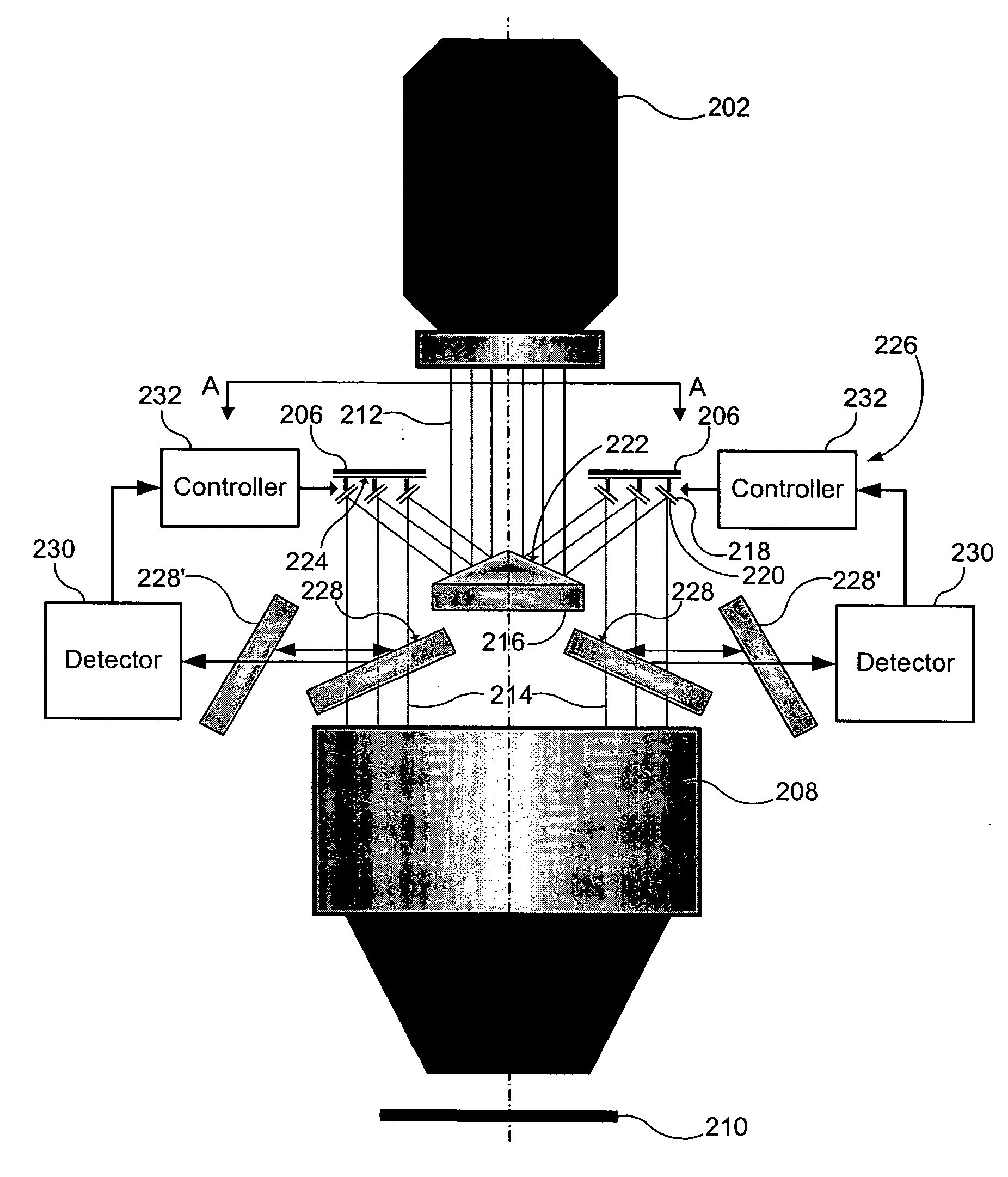
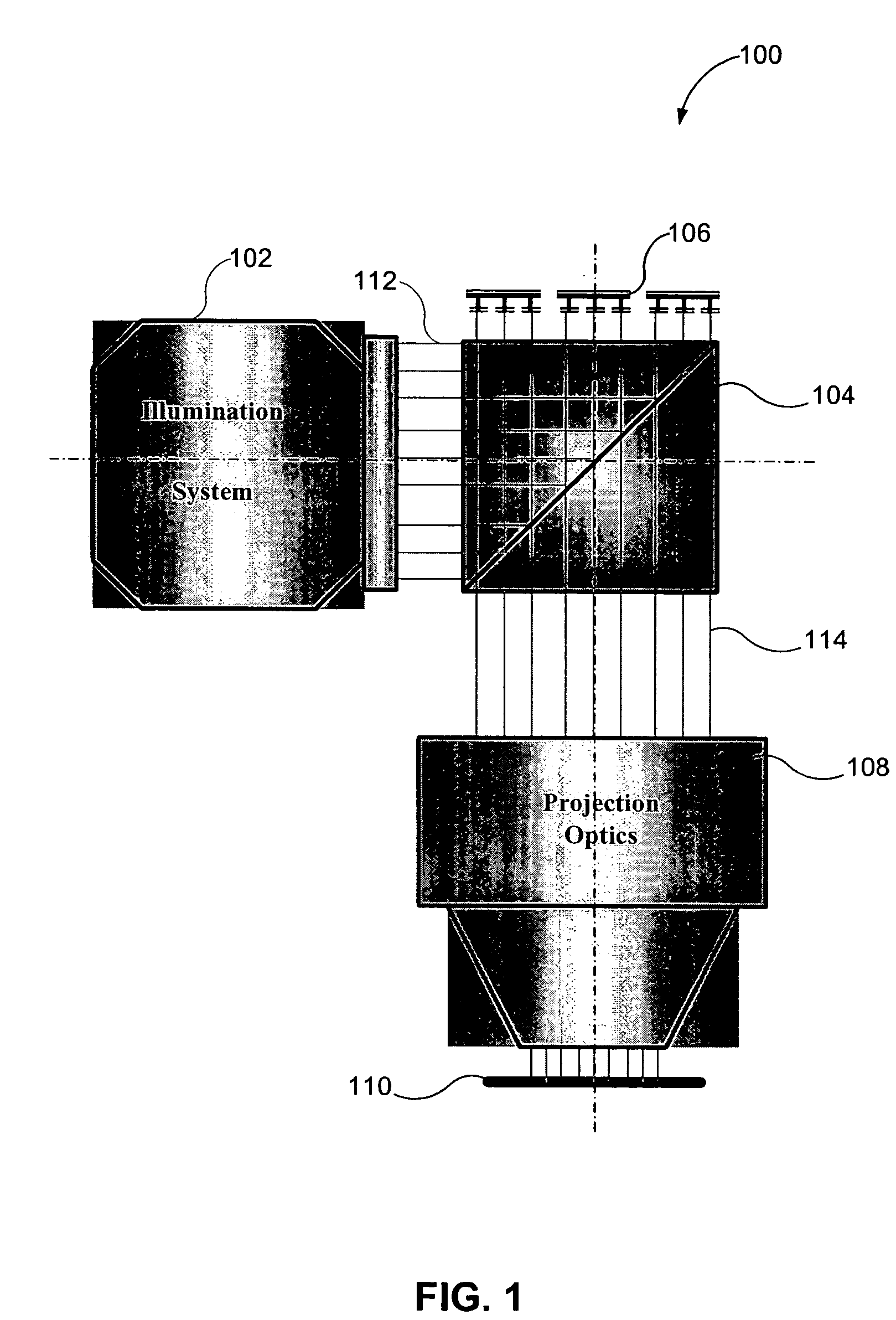
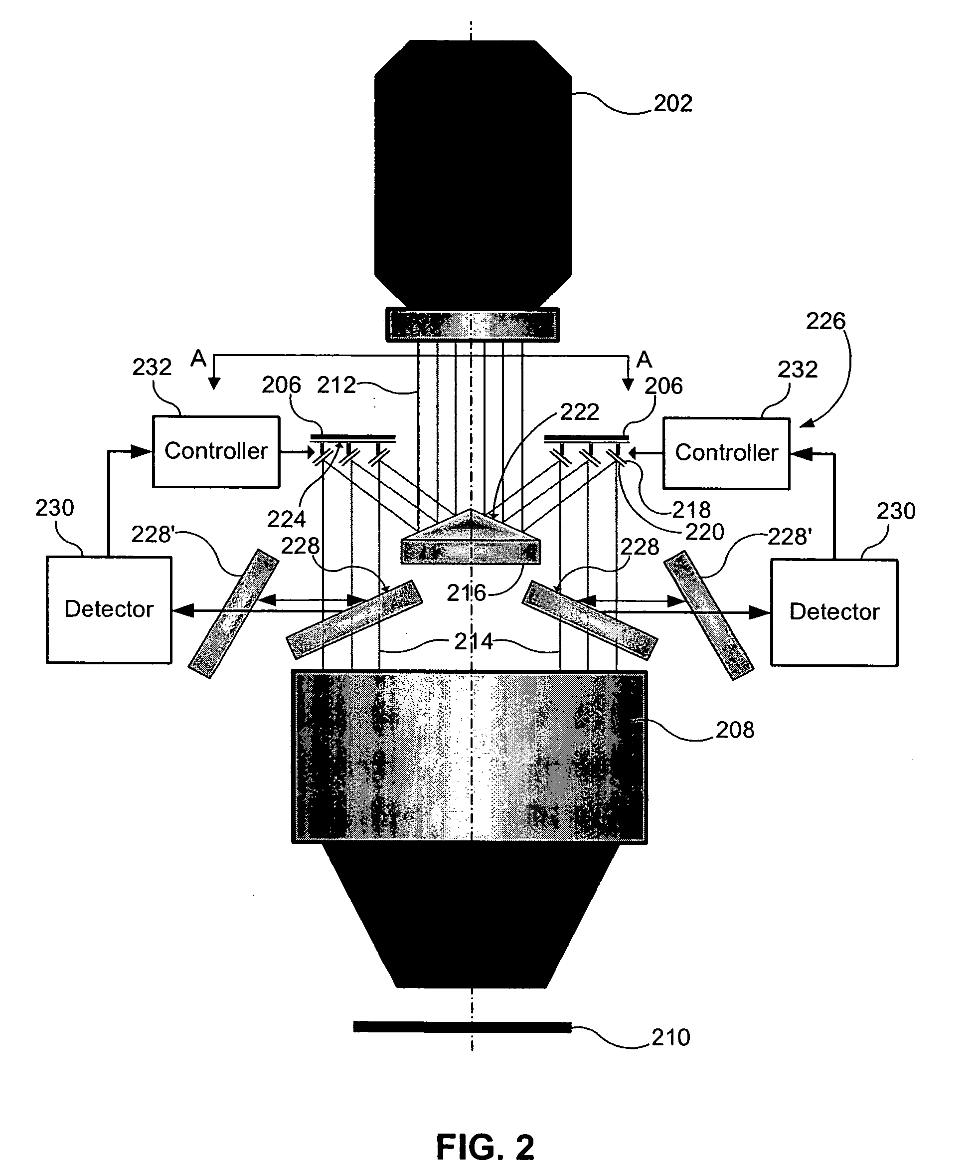
[0022] One or more embodiments of the present invention provide a system and method that are used to pattern illumination to form one or more devices on a substrate using a reflecting system, a pattern generator that defines an objection plane, a projection system, and the substrate that defines an image plane. A reflecting portion of the reflecting system is substantially parallel to a reflecting portion of the pattern generator in a default state. The reflecting portion of the pattern generator patterns the illumination beam and d...


PUM


Abstract

A system and method are used to pattern illumination to form one or more devices on a substrate using a reflecting system, a pattern generator that defines an objection plane, a projection system, and the substrate that defines an image plane. A reflecting portion of the reflecting system is substantially parallel to a reflecting portion of the pattern generator. The reflecting portion of the pattern generator patterns the illumination beam and directs the patterned illumination beam towards the substrate via the projection system. Based on the relationship of the reflecting system and the pattern generator, the illumination beam is telecentric proximate the object plane and the patterned illumination beam is telecentric proximate the image plane. Through use of a reflecting optic and not a transmissive optic to direct light between the illuminator and the projection system, illumination efficiency is increased and errors imparted on the illumination are decreased.

Description

BACKGROUND OF THE INVENTION [0001] 1. Field of the Invention [0002] The present invention is related to a lithography system. [0003] 2. Background Art [0004] In lithography systems, pattern generators are used to pattern substrates during an exposure process. Example lithography systems include, but are not limited to, reflective or transmissive maskless, immersion, and mask-based system. Example substrates include, but are not limited to, semiconductor wafers, flat panel display substrates, flexible substrates, and the like. Light interacting with an illumination spot on the pattern generator becomes patterned. The patterned light is projected using a projection optical system onto one or more target areas of the substrate during the exposure process to form features on a photosensitive material (e.g., a photoresist) on the substrate. [0005] In some applications of the lithography system, it is desired to have double telecentric illumination, which means that a chief ray of an illu...

Claims


Application Information

Patent Timeline
Patent Type & Authority Applications(United States)
IPC IPC(8): G03B27/54
CPCG03F7/70225G03F7/70291G03F7/70283
Inventor RHYZHIKOV, LEVVLADIMIRSKY, YULI
Owner ASML HLDG NV
Why Eureka
Try Eureka