
Optical arrangement, in particular projection exposure apparatus for EUV lithography, as well as reflective optical element with reduced contamination

a technology of euv lithography and exposure apparatus, which is applied in the direction of printers, instruments, active medium materials, etc., can solve the problems of limited vacuum pressure in the housing, inability to separate optical surfaces in its own right, and achieve the effect of reducing the adhesion of contamination

Active Publication Date: 2009-09-17
ASML NETHERLANDS BV +1
View PDF14 Cites 39 Cited by
  • Summary
  • Abstract
  • Description
  • Claims
  • Application Information

AI Technical Summary

Benefits of technology

[0011]At the same time the contamination reduction unit to a very large extent prevents any contaminating particles / molecules that are present in the vacuum housing or that enter said vacuum housing from reaching the optical surface. The present invention thus results in a reduction of contamination near the surface of the optical elements in that a mini-environment with a reduced number of contaminating particles / molecules, i.e. an ultra high vacuum, is generated around the optical surface so that fewer particles / molecules can deposit on the optical surface.
[0056]In a further, particularly advantageous, embodiment the adsorbent material is ruthenium. It has been known to cap multilayer systems for EUV lithography with a cover layer comprising rhodium, palladium, molybdenum, iridium, osmium, rhenium, silver, zinc oxide or their alloys or related alloys, particularly preferably ruthenium, because these materials have strongly catalytic characteristics. This characteristic becomes particularly clear during radiation of the surface in a typical EUV environment, which is dominated by water and hydrocarbon partial pressures, and in which almost always an increase in carbon as a result of the EUV radiation can be observed on the catalytic cover layer, i.e. the optical surface is contaminated by carbon, wherein the contamination increases as the length of time of radiation exposure increases. Experiments have shown that contamination by Sn and Zn atoms has a great affinity to deposit on pure ruthenium, in contrast to ruthenium surfaces that are contaminated with carbon and in which within the measuring errors practically no Sn and Zn atoms can be found. By placing a ring of ruthenium around the optical surface, which during radiation is not exposed to any EUV radiation and is thus not contaminated with carbon, the adherence of Sn and Zn contamination to the absorbent ring is significantly increased compared to the optical surface contaminated with carbon.

Problems solved by technology

This arrangement is disadvantageous in particular in that most of the materials used in the vacuum environment are not bakeable, so that the absolutely achievable vacuum pressure in the housing is limited by the outgassing of these materials.
On the other hand, the mere provision of partition walls for dividing the interior space does not in itself make it possible to separate the optical surfaces of non-optical elements that outgas contaminating substances, in particular if said optical elements are not bakeable.

Method used


Image

  • Optical arrangement, in particular projection exposure apparatus for EUV lithography, as well as reflective optical element with reduced contamination
  • Optical arrangement, in particular projection exposure apparatus for EUV lithography, as well as reflective optical element with reduced contamination
  • Optical arrangement, in particular projection exposure apparatus for EUV lithography, as well as reflective optical element with reduced contamination

Examples


Embodiment Construction

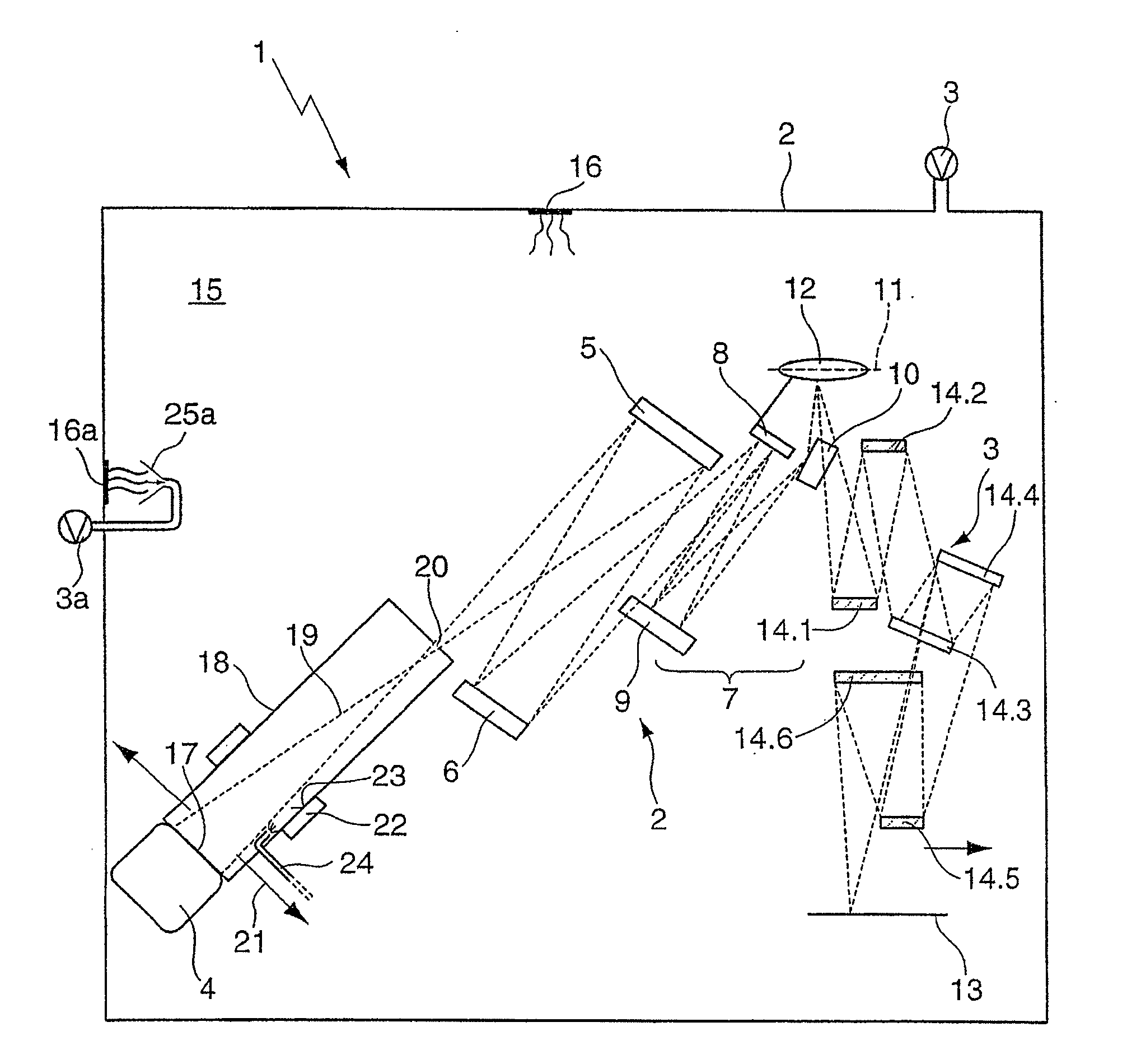
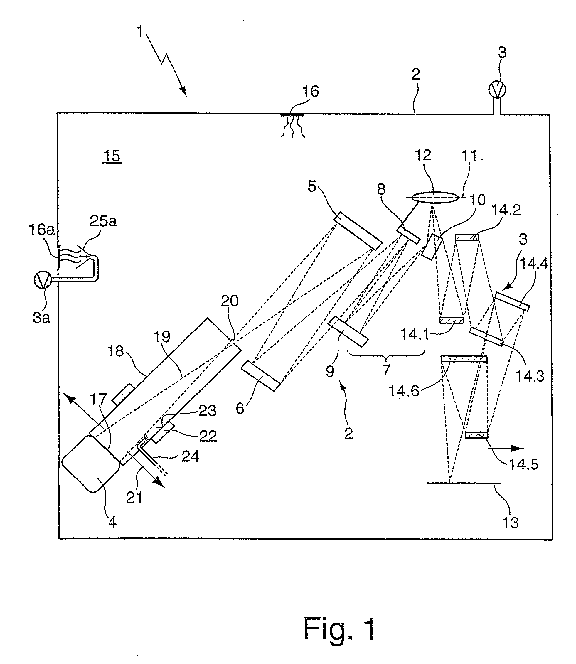
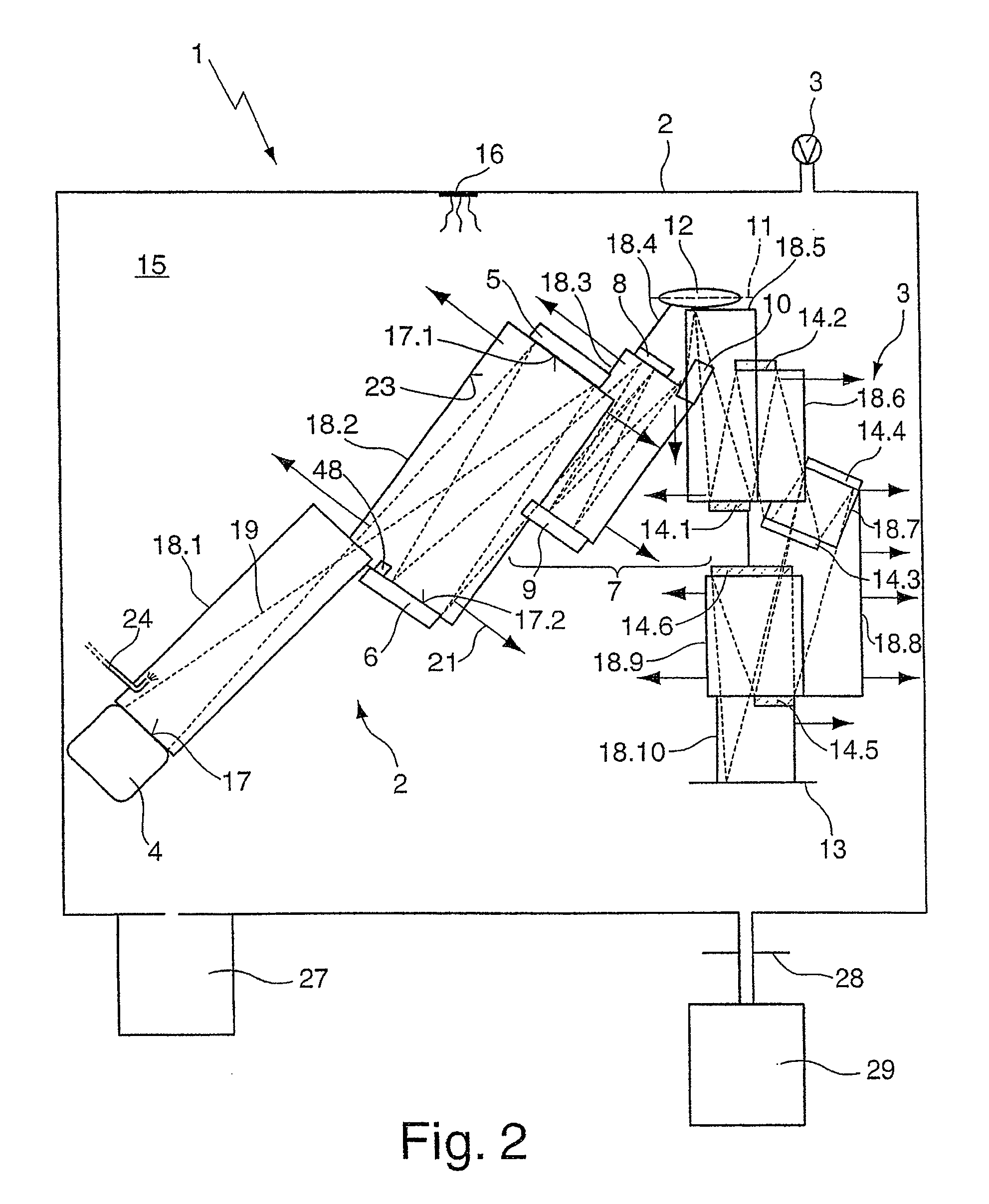
[0072]FIG. 1 shows a diagrammatic view of a projection exposure apparatus 1 for EUV lithography, including a housing 2 which is associated with a vacuum generating unit 3. The housing 2 is divided into three housing parts (not shown in FIG. 1) according to the optical functions of the components arranged in said housing 2, namely firstly a first housing part with a light generating unit 4 which for example includes a plasma light source and an EUV collector mirror for focusing the illumination radiation.

[0073]In a subsequent second housing part the illumination system is arranged which, following the path of the beam, has a mirror with field raster elements 5 and a mirror with pupil raster elements 6. A group of three mirrors, arranged downstream and acting as a telescopic lens 7 includes a first and a second mirror 8, 9 which are operated under normal incidence, as well as a third mirror 10 with negative refractive power, onto which mirror the light impinges at glancing incidence. ...


PUM


Abstract

An optical arrangement, in particular a projection exposure apparatus (1) for EUV lithography, includes: a housing (2) that encloses an interior space (15); at least one, in particular reflective, optical element (4 to 10, 12, 14.1 to 14.6) that is arranged in the housing (2); at least one vacuum generating unit (3) for generating a vacuum in the interior space (15) of the housing (2); and at least one vacuum housing (18, 18.1 to 18.10) that is arranged in the interior space (15) of the housing (2) and that encloses at least the optical surface (17, 17.1, 17.2) of the optical element (4 to 10, 12, 14.1 to 14.5), wherein a contamination reduction unit is associated with the vacuum housing (18.1 to 18.10), which contamination reduction unit reduces the partial pressure of contaminating substances, in particular of water and / or hydrocarbons, at least in close proximity to the optical surface (17, 17.1, 17.2) in relation to the partial pressure of the contaminating substances in the interior space (15).

Description

CROSS-REFERENCE TO RELATED APPLICATIONS[0001]This application is a Continuation of International Application PCT / EP2007 / 008113, with an international filing date of Sep. 18, 2007, which was published under PCT Article 21(2) in English, and the complete disclosure of which, including amendments, is incorporated into this application by reference. This application claims benefit under 35 U.S.C. §119(a) to German Patent Application No. 10 2006 044 591.0, filed on Sep. 19, 2006, the entire contents of which are hereby incorporated by reference.BACKGROUND TO THE INVENTION[0002]The invention relates to an optical arrangement, in particular a projection exposure apparatus for EUV lithography, comprising a housing that encloses an interior space, at least one, in particular reflective, optical element that is arranged in the housing, and at least one vacuum generating unit for generating a vacuum in the interior space of the housing. The invention further relates to a reflective optical ele...

Claims


Application Information

Patent Timeline
IPC IPC(8): B60R1/06
CPCB82Y10/00G03F7/70841G03B27/16G03F7/70916G21K2201/061G03F7/70883G03F7/20
Inventor EHM, DIRK HEINRICHMUELLENDER, STEPHANSTEIN, THOMASMOORS, JOHANNES HUBERTUS JOSEPHINAWOLSCHRIJN, BASTIAAN THEODOORKRAUS, DIETERVERSLUIS, RICHARDMEIJERINK, MARCUS GERHARDUS HENDRIKUS
Owner ASML NETHERLANDS BV
Learn More