Optical arrangement and EUV lithography device with at least one heated optical element, operating methods, and methods for cleaning as well as for providing an optical element

a technology of optical arrangement and lithography device, which is applied in the field of optical arrangement, can solve the problems of gradual reduction of radiation power, and achieve the effect of improving the optical characteristics of the optical arrangement and/or of the optical elemen

Inactive Publication Date: 2008-06-19
CARL ZEISS SMT GMBH +1
View PDF4 Cites 39 Cited by
  • Summary
  • Abstract
  • Description
  • Claims
  • Application Information

AI Technical Summary

Benefits of technology

[0010]It is an object of the invention to provide an optical arrangement, an EUV lithography device comprising such an optical arrangement, methods for operating such an optical arrangement and an EUV lithography device, re...

Problems solved by technology

However, as a rule, in the case of optical elements that are arranged further downstream in the beam path t...

Method used


Image

  • Optical arrangement and EUV lithography device with at least one heated optical element, operating methods, and methods for cleaning as well as for providing an optical element
  • Optical arrangement and EUV lithography device with at least one heated optical element, operating methods, and methods for cleaning as well as for providing an optical element
  • Optical arrangement and EUV lithography device with at least one heated optical element, operating methods, and methods for cleaning as well as for providing an optical element

Examples


Embodiment Construction

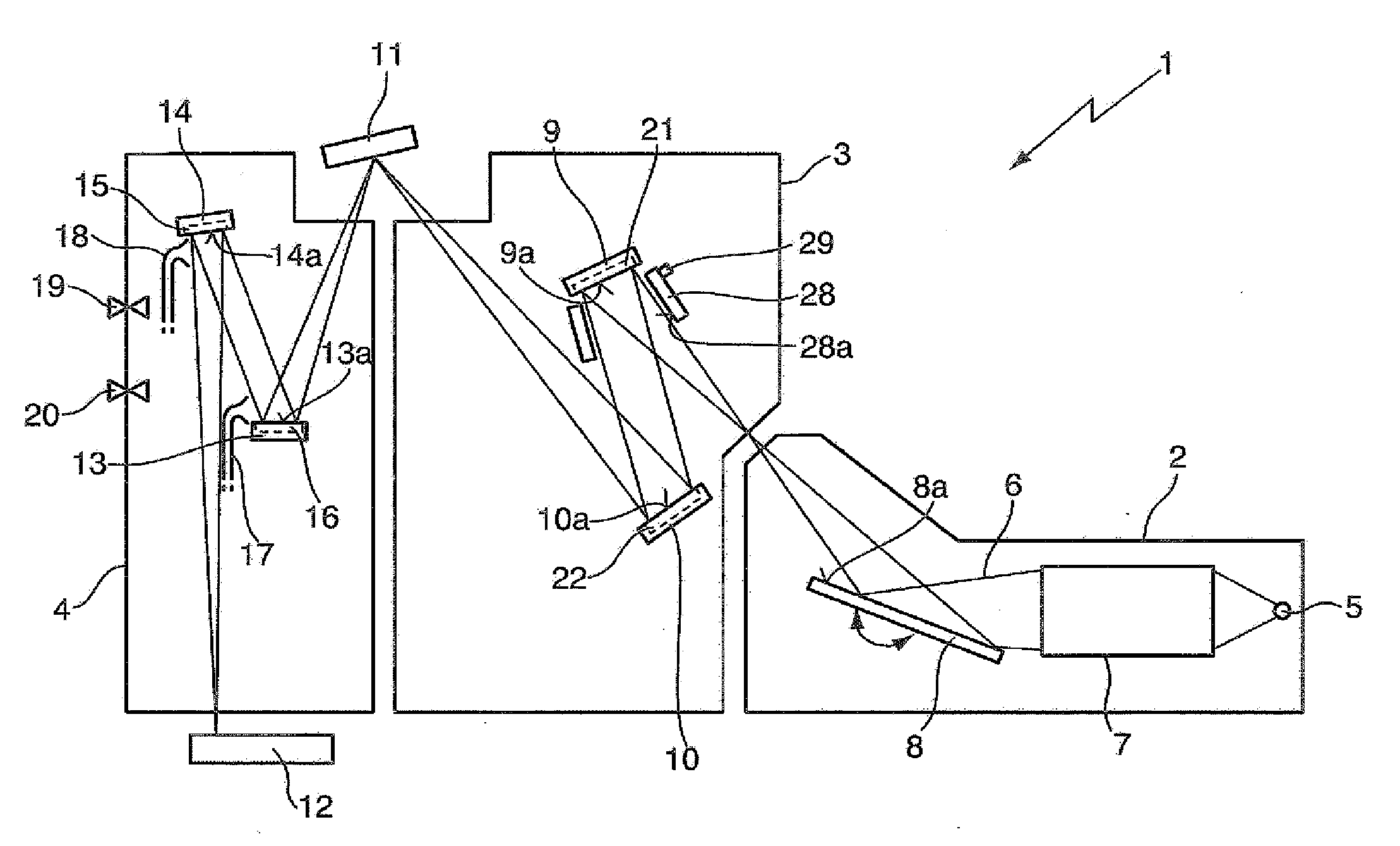
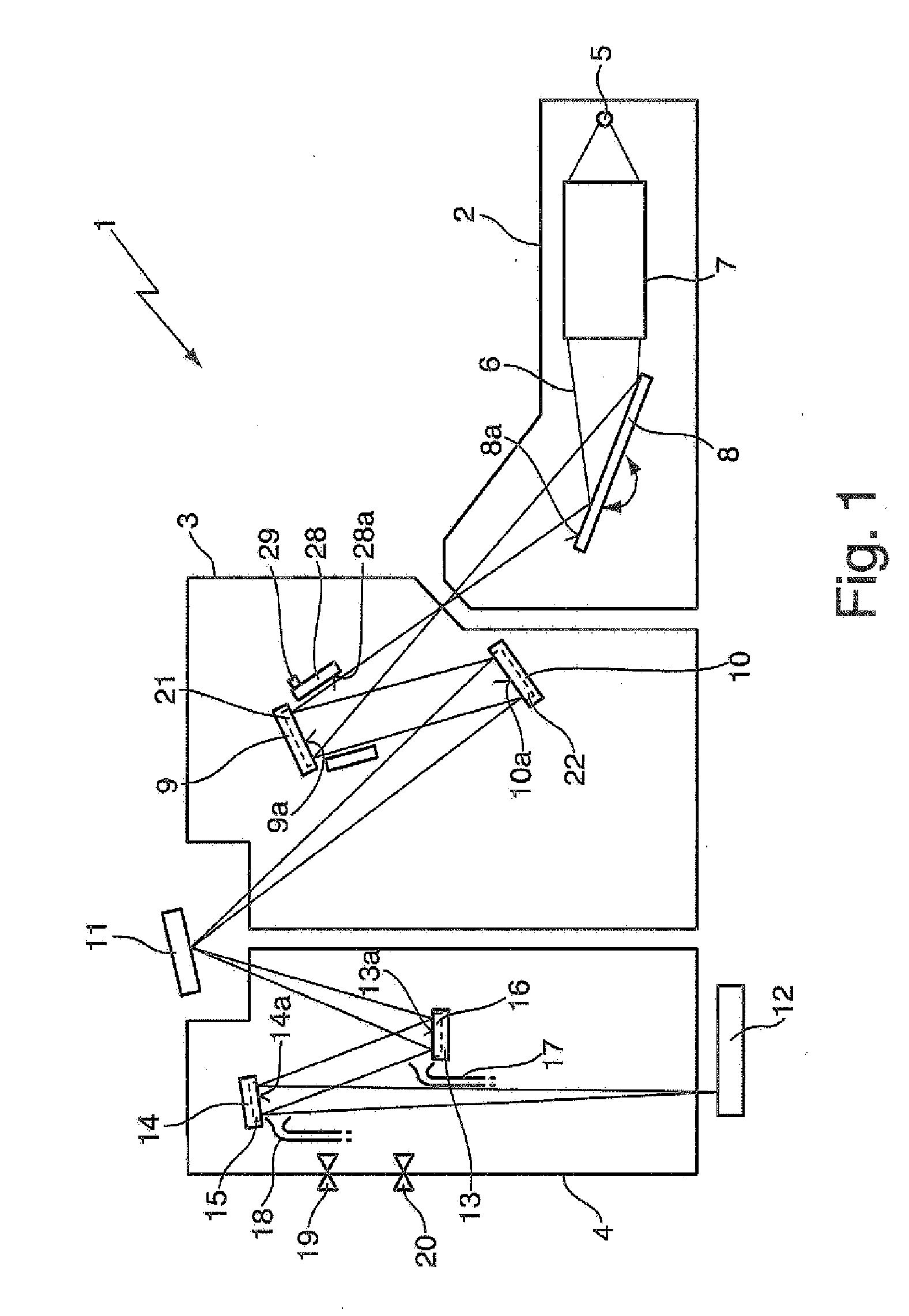
[0057]FIG. 1 diagrammatically shows an EUV lithography device 1 which comprises a beam shaping system 2, an illumination system 3 and a projection system 4 which are arranged one after the other in a beam path 6 which emanates from an EUV light source 5 of the beam shaping system 2. For example a plasma source or a synchrotron can be used as an EUV light source 5. The radiation emanating in the wavelength range of between approximately 5 nm and approximately 20 nm is first concentrated in a collimator 7. By means of a subsequent monochromator 8, by varying the angle of incidence, as indicated by a double arrow, the desired operating wavelength is filtered out.

[0058]The radiation treated in the beam shaping system 2 as far as wavelength and spatial distribution is concerned is introduced into the illumination system 3 that comprises a first and a second reflective optical element 9, 10. The two reflective optical elements 9, 10 guide the radiation onto a photomask 11 as a further ref...


PUM


Abstract

An optical arrangement, in particular a projection system, illumination system or beam shaping system for EUV lithography, including at least one optical element that is arranged in a beam path of the optical arrangement and that reflects radiation in the soft X-ray- or EUV wavelength range, wherein at least during operation of the optical arrangement at least one of, preferably each of, the reflective optical elements in the beam path, at least at the optical surface, has an operating temperature of approximately 30° C. or more, preferably of approximately 100° C. or more, particularly preferably of approximately 150° C. or more, and even more preferably of approximately 250° C. or more, and wherein the optical design of the at least one reflective optical element is selected such that its optical characteristics are optimised for operation at the operating temperature. Also presented is a method for providing a reflective optical element with such an optical design.

Description

CROSS-REFERENCE TO RELATED APPLICATIONS[0001]This application claims the benefit under 35 U.S.C. 119(e)(1) of U.S. Provisional Application No. 60 / 946,439, filed Jun. 27, 2007, the entire contents of which are hereby incorporated by reference. This application also claims priority under 35 U.S.C. 119(a) to German Patent Application No. 10 2007 030 162.8 filed on Jun. 27, 2007, the entire contents of which are hereby incorporated by reference. This application further claims priority under 35 U.S.C. 119(a) to German Patent Application No. 10 2006 042 987.7, filed on Sep. 13, 2006, the entire contents of which are hereby incorporated by reference.FIELD AND BACKGROUND OF THE INVENTION[0002]The invention relates to an optical arrangement, in particular a projection system, an illumination system or a beam shaping system for EUV lithography, to an EUV lithography device comprising such an optical arrangement, to methods for operating such an optical arrangement and an EUV lithography devi...

Claims


Application Information

Patent Timeline
IPC IPC(8): G03B27/52G21K5/00
CPCB82Y10/00G03F7/70316G03F7/70891G21K2201/067G03F7/70958G21K1/062G21K2201/061G03F7/70925
Inventor EHM, DIRK HEINRICHVAN DE RUNSTRAAT, ANNEMIEKEWOLSCHRIJN, BASTIAAN THEODOORSTORM, ARNOLDUS JANSTEIN, THOMASMEIJERINK, MARCO G. H.BASTEIN, A. G. TON M.VAN SOEST-VERCAMMEN, ESTHER L. J.KOSTER, NORBERTUS BENEDICTUSGUBBELS, FRITS G. H. M.OPREL, PETER J.NIENOORD, MICHIELRIEPEN, MICHELMOORS, JOHANNES HUBERTUS JOSEPHINA
Owner CARL ZEISS SMT GMBH
Why Eureka
Try Eureka