Enhanced reflective optical encoder

a reflective optical encoder and reflective technology, applied in the direction of converting sensor output, sensing record carriers, instruments, etc., can solve the problems of limiting the speed and resolution the complexity of the optical encoder, and the packaging design of the transmitting optical encoder

Active Publication Date: 2006-05-11
AVAGO TECH INT SALES PTE LTD
View PDF3 Cites 36 Cited by
  • Summary
  • Abstract
  • Description
  • Claims
  • Application Information

AI Technical Summary

Benefits of technology

[0024] An Enhanced Reflective Optical Encoder (“EROE”) having an emitter module for transmitting emitted optical radiation to an encoded media and a detector module for receiving reflected optical radiation from the encoded media is disclosed. The EROE may include a transmissive layer covering both the emitter module and the detector module. The EROE may include an optical isolation element located within the transmissive layer and located between the emitter module and the detector module. The optical isolation element reduces undesired optical radiation transmitted from the emitter module to the detector module, where the undesired optical radiation is a portion of the emitted optical radiation.
[0025] Alternatively, the EROE may include an optical isolation element located on top of the transmissive layer and located between the emitter module and the detector module. The optical isolation element reduces undesired optical radiation transmitted from the emitter module to the detector module, where the undesired optical radiation is a portion of the emitted optical radiation.

Problems solved by technology

Unfortunately, however, transmissive optical encoders require packaging designs with high profiles because the emitter module and detector module to be placed opposite each other around the encoder media.
Unfortunately, typical reflective optical encoders suffer from lower contrast capabilities than transmissive optical encoders and therefore have limits in speed and resolution compared to transmissive optical encoders.
However, imaging optical encoders require a diffusive encoded media that at present is not maturely established technologically.
Additionally, imaging optical encoders suffer from diffusive reflectance and also have limits in speed and resolution compared to transmissive optical encoders.
Unfortunately, a problem with this type of reflective optical encoder 600 is that undesired optical radiation 618 from the emitter module 606 is propagated through the epoxy to the detector module 608 causing noise in the detector module 608 that results in loss of image contrast of the light and dark regions (i.e., the “bars”) on the encoded media 602.
This loss in image contrast limits the speed and resolution of the typically known reflective optical encoder 600.

Method used


Image

  • Enhanced reflective optical encoder
  • Enhanced reflective optical encoder
  • Enhanced reflective optical encoder

Examples


Embodiment Construction

[0043] In the following description, reference is made to the accompanying drawings that form a part hereof, and which show, by way of illustration, a specific embodiment in which the invention may be practiced. Other example of implementation may be utilized and structural changes may be made without departing from the scope of the present invention.

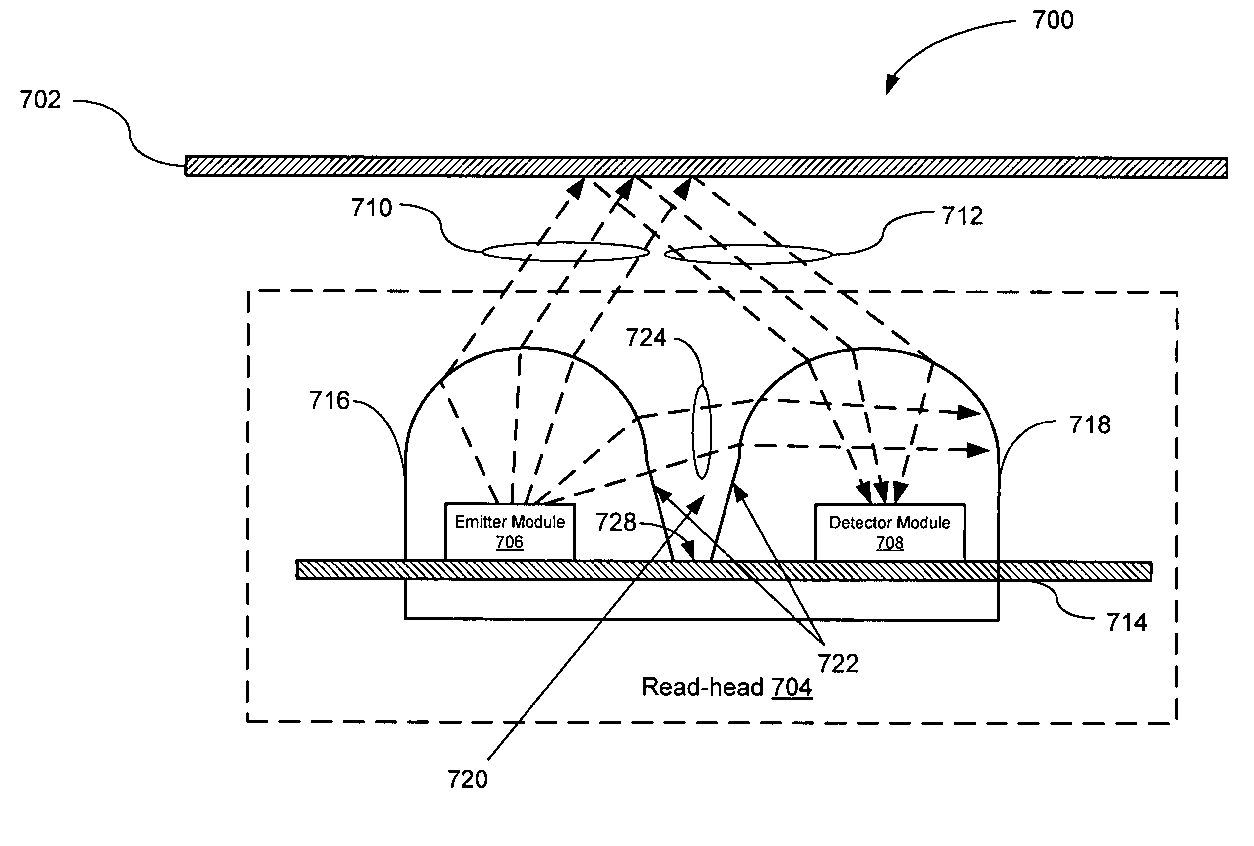
[0044] As stated above, a problem with known types of reflective optical encoders is that undesired optical radiation from the emitter module is propagated through the epoxy to the detector module causing noise in the detector module, which results in loss of image contrast of the light and dark regions (i.e., the “bars”) on the encoded media. This loss in image contrast limits the speed and resolution of typical known reflective optical encoders. In response, an Enhanced Reflective Optical Encoder (“EROE”) is described that is capable of providing higher image contrast and resolution than known reflective optical encoders. The EROE ma...


PUM


Abstract

An Enhanced Reflective Optical Encoder (“EROE”) having an emitter module for transmitting emitted optical radiation to an encoded media and a detector module for receiving reflected optical radiation from the encoded media. The EROE may include a transmissive layer covering both the emitter module and the detector module, and an optical isolation element located within the transmissive layer and located between the emitter module and the detector module. The optical isolation element reduces undesired optical radiation transmitted from the emitter module to the detector module, where the undesired optical radiation is a portion of the emitted optical radiation.

Description

BACKGROUND OF THE INVENTION [0001] Sensors are key feedback devices on many electromechanical systems. There is a wide variety of sensors available and new sensor technologies are continuously being developed. One of the most common position sensors utilized to measure the moving parts within a mechanical system is the optical encoder. An optical encoder is a closed-feedback device that converts motion or positional information into digital signals that may be utilized by a motor control system. [0002] Optical encoders produce a digital output based on an encoded media (such as a codewheel or codestrip) that passes either through or by the optical encoder. In general, this encoded media is encoded with alternating light and dark regions (or slots) on the surface of the encoded media. When operated in conjunction with this encoded media, the optical encoder translates rotary or linear motion into a two-channel digital output. [0003] Typically, optical encoders are either linear optic...

Claims


Application Information

Patent Timeline
Patent Type & Authority Applications(United States)
IPC IPC(8): G06K7/10
CPCG01D5/34715
Inventor FOO, SIANG LEONGWONG, WENG FEICHIN, YEE LOONG
Owner AVAGO TECH INT SALES PTE LTD
Why Eureka
Try Eureka