Catoptric projection optical system and exposure apparatus

a projection optical system and catoptric technology, applied in the field of reflection type or catoptric projection optical system, can solve the problems of difficult to meet this requirement using, conventional three or four mirrors have a difficulty in reducing wave front aberration, and the projection optical system cannot include any lenses, etc., to achieve excellent imaging performance, reduce the maximum effective diameter and the overall length of the optical system, and achieve excellent imaging performance.

Inactive Publication Date: 2005-07-26
CANON KK
View PDF9 Cites 37 Cited by
  • Summary
  • Abstract
  • Description
  • Claims
  • Application Information

AI Technical Summary

Benefits of technology

[0011]Accordingly, it is an exemplified object of the present invention to provide a six-mirror catoptric projection optical system with a high NA and excellent imaging performance, and an exposure apparatus using the same, which are applicable to the EUV lithography, and reduce a maximum effective diameter and an overall length of the optical system.

Problems solved by technology

The recent trend has required that the resolution be a smaller value; however it is difficult to meet this requirement using only the increased NA, and the improved resolution expects use of a shortened wavelength.
No applicable glass materials have been proposed for the EUV light as exposure light, and a projection optical system cannot include any lenses.
Nevertheless, conventional three or four mirrors have a difficulty in reducing wave front aberration.

Method used


Image

  • Catoptric projection optical system and exposure apparatus
  • Catoptric projection optical system and exposure apparatus
  • Catoptric projection optical system and exposure apparatus

Examples


Embodiment Construction

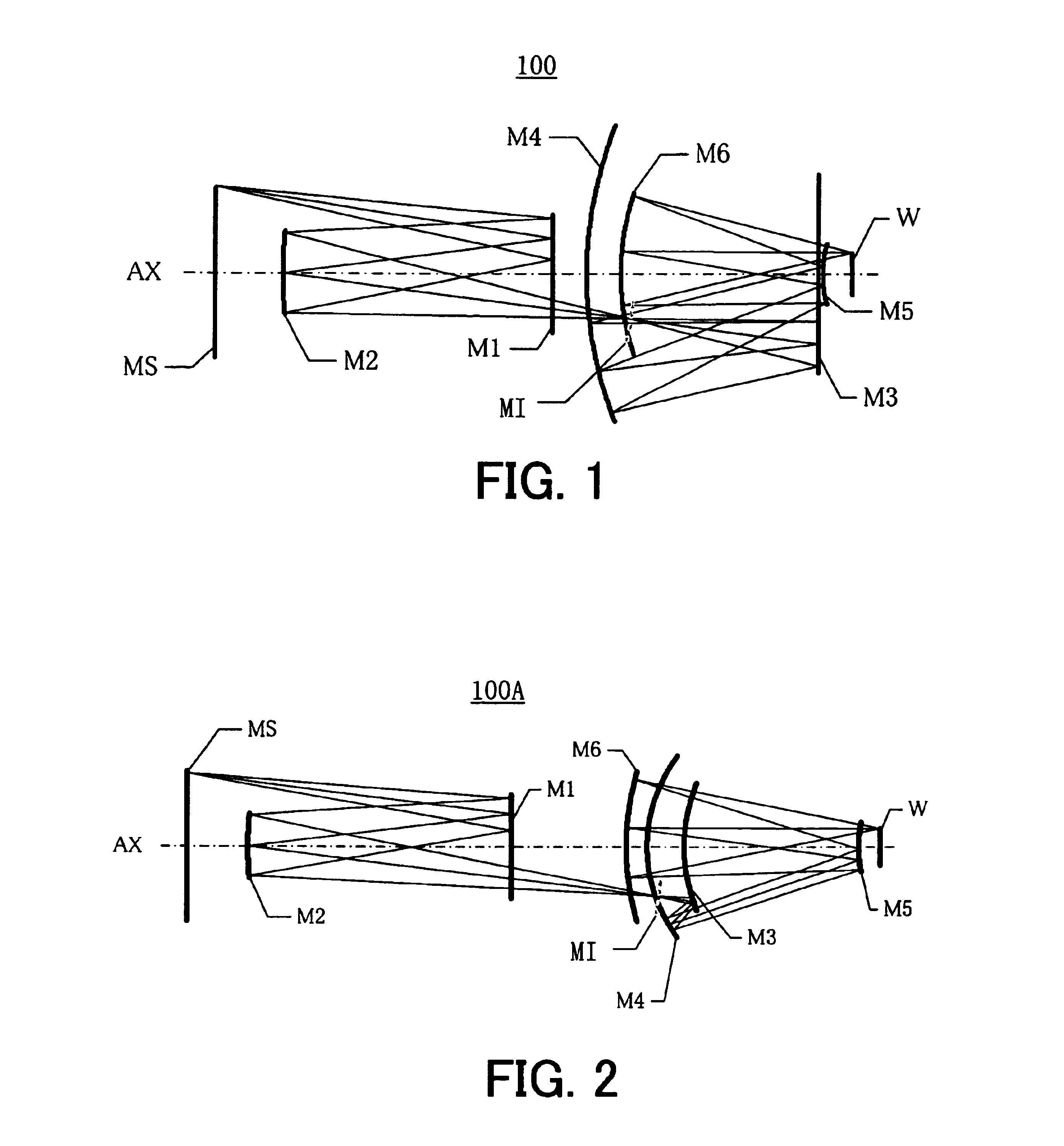
[0025]In providing a six-mirror catoptric projection optical system with a high NA and excellent imaging performance, and an exposure apparatus using the same, which are applicable to the EUV lithography, and reduce a maximum effective diameter and an overall length of the optical system, the instant inventor has earnestly studied a mirror's effective diameter, and discovered that a small angle of a principal ray at an intermediate image position (smaller than sin−1NA) and a small distance between the intermediate image position and the exit pupil contribute to a reduction of the effective diameter.

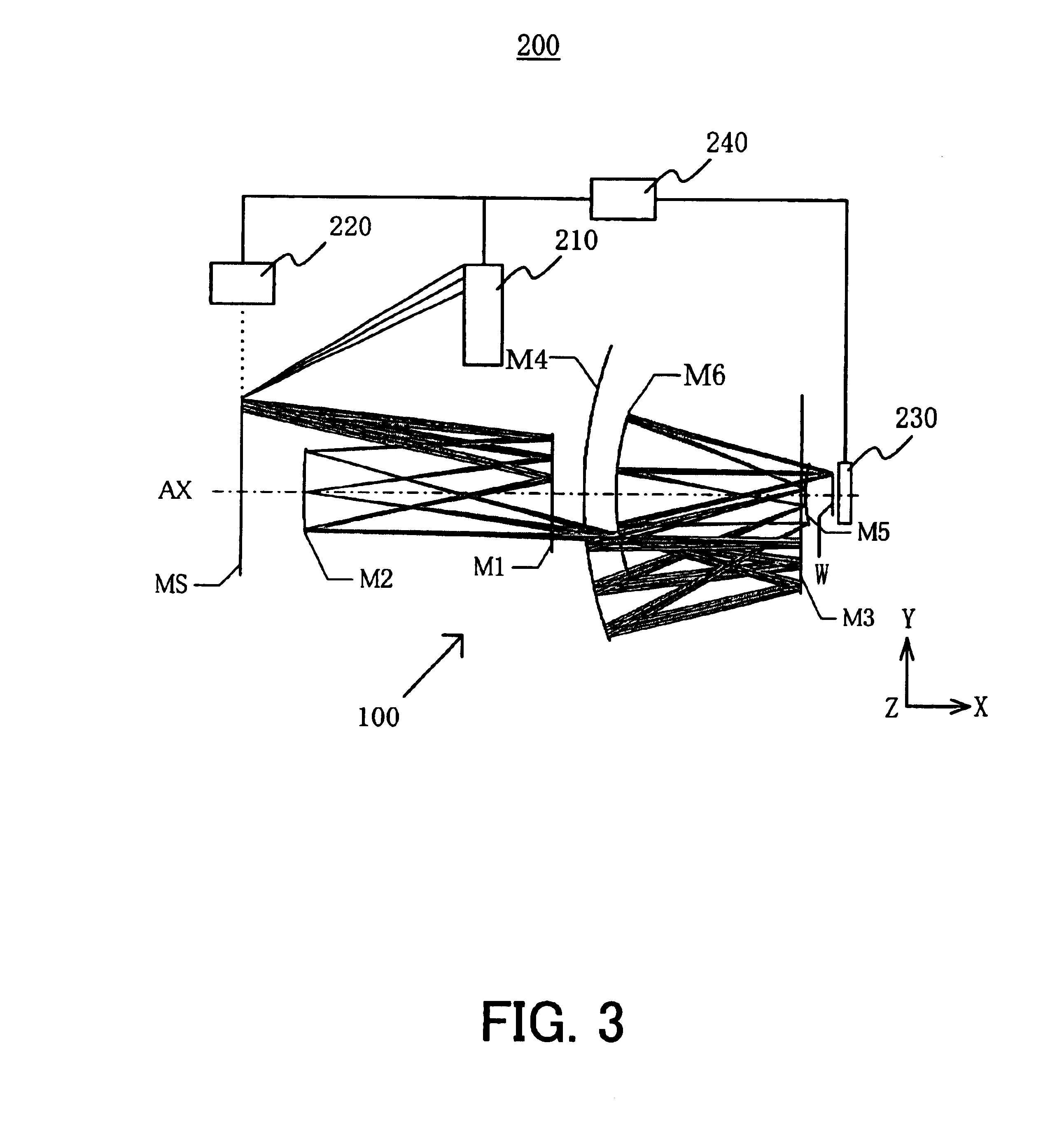
[0026]A description will now be given of catoptric projection optical systems 100 and 100A and an exposure apparatus 200 as one aspect of the present invention with reference to the accompanying drawings. The same reference numeral in each figure denotes the same element, and a description thereof will be omitted. Here, FIG. 1 is a schematic structure of the catoptric projection optical s...


PUM

PropertyMeasurementUnit
wavelengthaaaaaaaaaa
incident angleaaaaaaaaaa

Abstract

A catoptric projection optical system for projecting a reduced size of a pattern on an object surface onto an image surface and for serving as an imaging system that forms an intermediate image between the object surface and image surface, includes six or more mirrors, wherein a position of an exit pupil with respect to the intermediate image is located between the object surface and image surface, and wherein the largest angle between principal rays and an optical axis for angles of view at the position of the exit pupil is sin−1NA or smaller, where NA is a numerical aperture at the side of the image surface.

Description

[0001]This application claims a benefit of priority based on Japanese Patent Application No. 2003-044886, filed on Feb. 21, 2003, which is hereby incorporated by reference herein in its entirety as if fully set forth herein.BACKGROUND OF THE INVENTION[0002]The present invention relates generally to an exposure apparatus, and more particularly to a reflection type or catoptric projection optical system, and an exposure apparatus using the same which use ultraviolet (“UV”) and extreme ultraviolet (“EUV”) light to expose an object, such as a single crystal substrate for a semiconductor wafer, and a glass plate for a liquid crystal display (“LCD”).[0003]Recent demands for smaller and lower profile electronic devices have increasingly demanded finer semiconductor devices to be mounted onto these electronic devices. For example, the design rule for mask patterns has required that an image with a size of a line and space (“L & S”) of less than 0.1 μm be extensively formed. It is expected t...

Claims


Application Information

Patent Timeline
Patent Type & Authority Patents(United States)
IPC IPC(8): G02B17/06G02B17/00G03F7/20G02B27/18H01L21/027
CPCG02B17/0657G03F7/70275G03F7/70233G03F7/2008
Inventor SUNAGA, TOSHIHIROHATAKEYAMA, KOSHISASAKI, TAKAHIRO
Owner CANON KK
Why Eureka
Try Eureka