Compact, wide-field-of-view imaging optical system

a wide-field-of-view imaging and optical system technology, applied in the field of compact, wide-field-of-view imaging optical systems, can solve the problems of low signal-to-noise ratio, difficult to design a compact, light-weight wfov optical system, and required long exposure time to produce usable images, etc., to achieve a large numerical aperture and high signal-to-noise ratio

Active Publication Date: 2005-12-08
RAYTHEON CO
View PDF2 Cites 23 Cited by
  • Summary
  • Abstract
  • Description
  • Claims
  • Application Information

AI Technical Summary

Benefits of technology

[0012] The present approach provides a WFOV imaging optical system that is more compact than conventional WFOV optical systems such as the inverse telephoto optical system. The length of the present WFOV imaging optical system is typically one-half or less of the length of the inverse telephoto optical system having the same field of view. The present approach also has a large numerical aperture, leading to a high signal-to-noise ratio for the imaging optical system.

Problems solved by technology

It is therefore difficult to design a compact, light-weight WFOV optical system.
Additionally, the numerical aperture of the inverse telephoto lens is typically relatively small, resulting in a low signal-to-noise ratio and a required long exposure time to produce a usable image.

Method used


Image

  • Compact, wide-field-of-view imaging optical system
  • Compact, wide-field-of-view imaging optical system
  • Compact, wide-field-of-view imaging optical system

Examples


Embodiment Construction

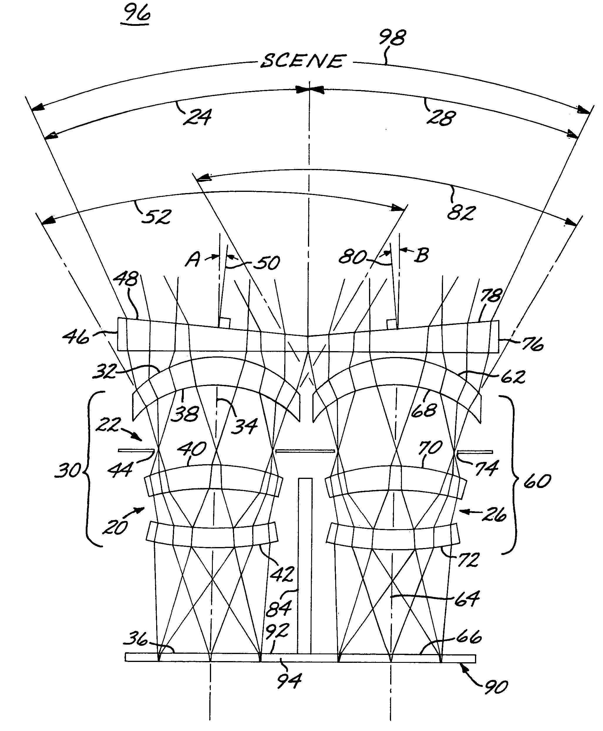
[0018]FIG. 1 depicts an imaging optical system 20. The imaging optical system 20 includes a first imaging structure 22 having a first field of view 24, and a second imaging structure 26 parallel to the first imaging structure 22 and having a second field of view 28 different from the first field of view 24.

[0019] The first imaging structure 22 includes a first lens module 30 having a first-lens-module input end 32 closest to the scene, a first optical axis 34, and a first focal plane 36. The depicted preferred embodiment of the first lens module 30 includes a first lens 38, a second lens 40, and a third lens 42, although other specific lens arrangements may be used. The first lens 38 is between the input end 32 and an aperture stop 44, and the second lens 40 and third lens 42 are between the aperture stop 44 and the first focal plane 36. The lenses of the first lens module 30 are selected to image light rays entering the input end 32 from a scene onto the first focal plane 36. The ...


PUM


Abstract

An imaging optical system includes a first imaging structure having a first optical axis and a first field of view, wherein the first imaging structure forms an image on a common focal plane, and a second imaging structure having a second optical axis parallel to the first optical axis and a second field of view different from the first field of view, wherein the second imaging structure forms an image on the common focal plane. The imaging structures preferably contain identical lens modules, most preferably identical Petzval lenses, and achromatic or apochromatic prisms of different spatial orientations. A planar sensor structure lies in the common focal plane, wherein the first optical axis and the second optical axis pass through the planar sensor structure.

Description

[0001] This invention relates to a wide-field-of-view optical system and, more particularly, to such an optical system having a short physical length and a small size. BACKGROUND OF THE INVENTION [0002] Wide-field-of-view (WFOV) imaging optical systems are used in a number of applications. For example, surveillance systems, helmet-mounted sensors, missile warning sensors for aircraft, and space and aircraft acquisition sensors all may use WFOV optical systems. In this context, a WFOV optical system typically seeks a field of view of at least 60 degrees in at least one dimension. [0003] Most WFOV imaging optical systems are of the inverse telephoto or fisheye type. The inverse telephoto optical system has a front (that is, nearest the scene) lens or lens group with a negative optical power, in order to view a wide field of view, and a rear (that is, nearest the eye or the sensor) lens or lens group with a positive optical power to focus the light rays onto the focal plane. This distr...

Claims


Application Information

Patent Timeline
Patent Type & Authority Applications(United States)
IPC IPC(8): G02B13/06G02B13/08G02B23/18H04N5/225
CPCG02B13/06G02B23/18H04N5/2254H04N5/23238H04N23/55H04N23/698
Inventor CHEN, CHUNGTE W.ANDERSON, J. STEVE
Owner RAYTHEON CO
Why Eureka
Try Eureka