Method and device for measuring, calibrating and using laser tweezers

a laser tweezer and laser tweezer technology, applied in the direction of optical radiation measurement, diaphragm, immobilised enzymes, etc., can solve the problems of difficult repeating measurements using the same particle, high equipment requirements, and high equipment requirements, and achieves increased electrical control signals and numerical apertures high.

Inactive Publication Date: 2006-01-31
EVOTEC BIOSYST +1
View PDF3 Cites 24 Cited by
  • Summary
  • Abstract
  • Description
  • Claims
  • Application Information

AI Technical Summary

Benefits of technology

[0023]According to a third important aspect of the invention, microscopic particles in a microelectrode arrangement with the cited (at least) two minimum field levels with relative, set field force can be at least temporarily positioned or joined into groups or aggregates, or the groups or aggregates can be divided into parts. The manipulation of the aggregates according to the invention is preferably combined with the above-cited aspects of the invention; it can also be used independently within predetermined (if unknown) electrical and / or optical field strengths.
[0024]The subject to the invention is also a microsystem that is adapted to create an optoelectric double cage that is generated by the simultaneous creation of at least two minimum field levels of an electrical capture area and an optical cage. A fluid microsystem possesses a microelectrode arrangement to generate the electrical capture area and a transparent structure for creating the optical cage within the microelectrode arrangement. The microsystem is preferably a fluid microsystem that can be open on one side facing the light source to generate the optical cage.
[0025]It is to be noted that the techniques used to according to the invention for creating the microsystem, generating the electrical field strengths, and generating the optical cage are known as such so that details will not be discussed in the following description.
[0026]In the following, general explanations of basic principles of the invention will first be provided.
[0027]In the laser trapping process, a particle can be held in a local equilibrium that is formed by an optical trap or an optical cage in the focus of at least one laser beam. In a high-frequency microfield cage, a particle can be held in a local equilibrium that is formed by an electrical capture area of the respective field distribution. The capture area can be formed by a point, a line, or an area depending upon the field distribution. In the following description, in a non-restrictive manner the capture area will be referred to as a point; the invention can, however be correspondingly implemented using any shape of capture area. According to the above-cited first aspect, the invention is especially based on measuring the optically-induced forces in the optical trap (optical cage) consisting of the electrical force exerted on the particle when it changes between the states of equilibrium, i.e., from the focus to the capture point or vice versa The object is hence especially solved by means of laser trapping in an electrical high-frequency micro fieldcage whose field strength and electrical field distribution are known, and that is adapted to inject the laser light required to form the optical cage. By shifting the particle trapped in the laser trap (focus) from the capture point of the field cage at low electrical trap power into a specific position at a distance from the capture point, the threshold can be precisely determined at which the electrical field returns the particle from the optical focus to the capture point or vice versa by subsequently increasing the amplitude of the electrical control signals of the field cage.
[0028]The laser light required to form the optical cage is injected by means of various design features of the microfield cage. Among these are in particular attaching at least one partial group of electrodes of the microfield cage to a substrate that is transparent and thin enough for a laser light source to be brought close enough to the microfield cage so that the focus forms in it. In practical designs of the laser tweezers, the laser light source comprises an coupling lens with a very high numerical aperture. The focal length is normally in the range of a few hundred micrometers. The preferred thickness of the transparent substrate is therefore less than the focal length of the laser light source.

Problems solved by technology

A previously unsolved problem is how to measure the actual optically-induced force in the optical field (laser trap) acting on a particle.
There are several extremely time-consuming methods to do this requiring much equipment that can be summarized as follows:
A disadvantage of this procedure is that it is difficult to repeat measurements using the same particle, and very complicated channel structures are required to make measurements in different spatial directions.
A three-dimensional measurement of force (x, y, z) is not possible.
This procedure is also limited to certain particle shapes (spheres, ellipsoids) with smooth surfaces.

Method used


Image

  • Method and device for measuring, calibrating and using laser tweezers
  • Method and device for measuring, calibrating and using laser tweezers
  • Method and device for measuring, calibrating and using laser tweezers

Examples


Embodiment Construction

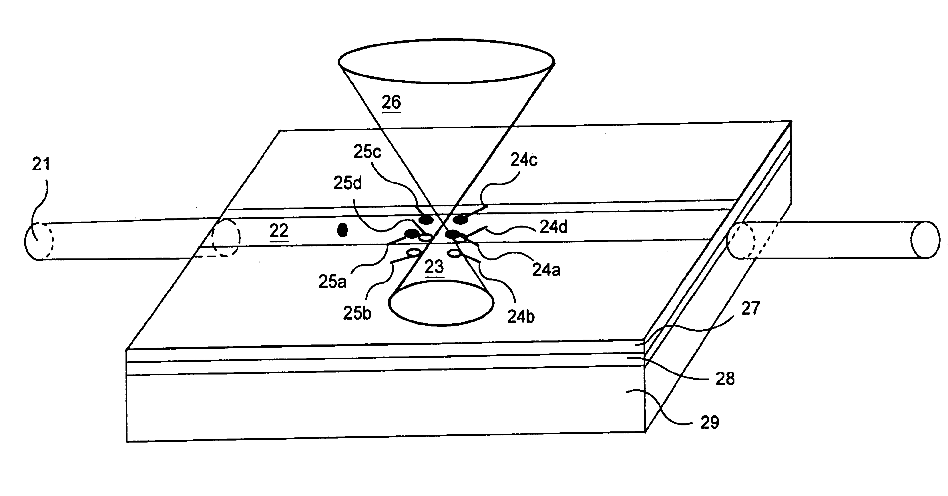
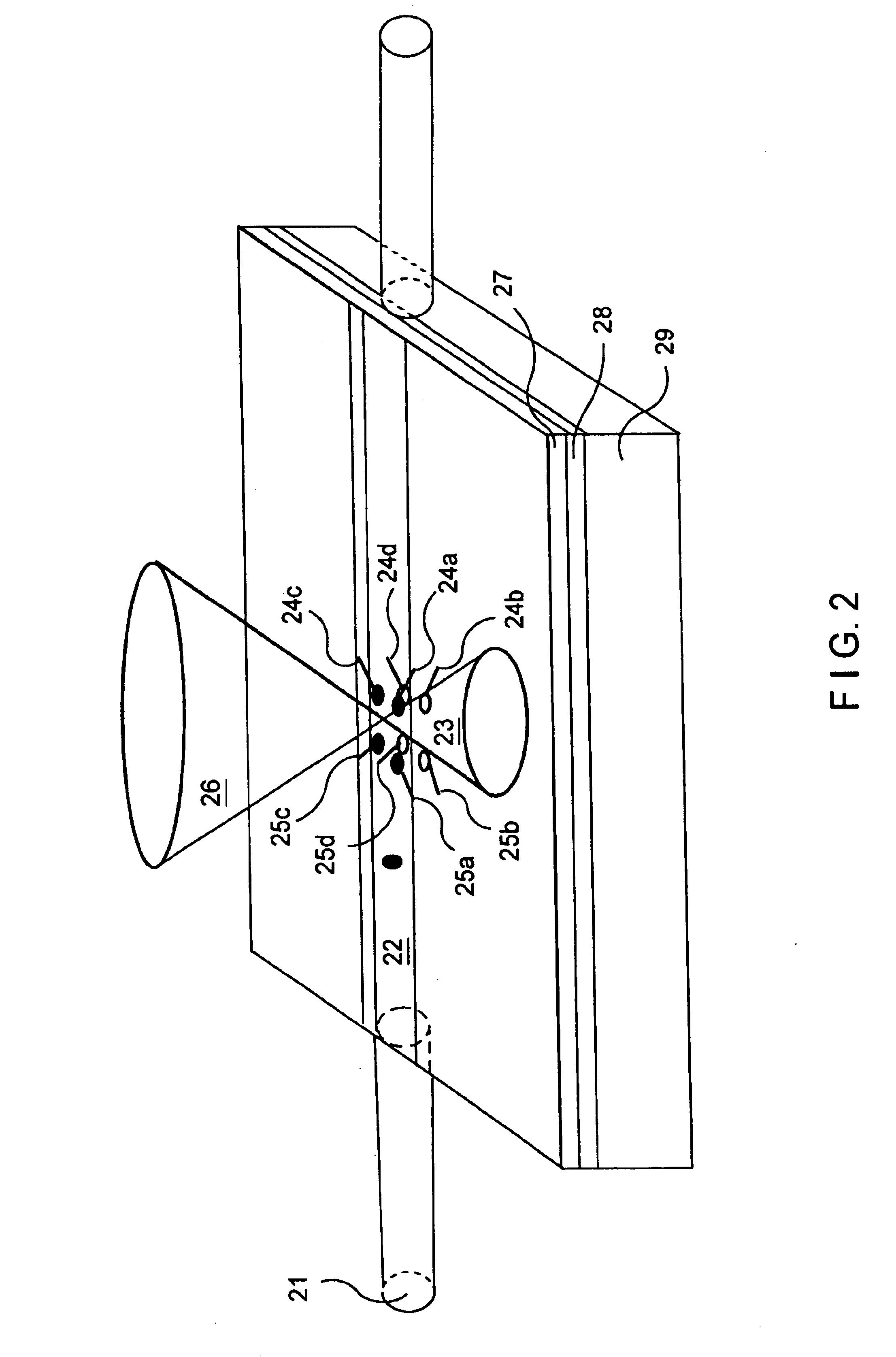
[0044]The invention will be described in the following referring to the combination of an octopole field cage to form the capture area and an individual capture laser to form the optical cage. The invention can however be realized with any field cage shape or several laser beams.

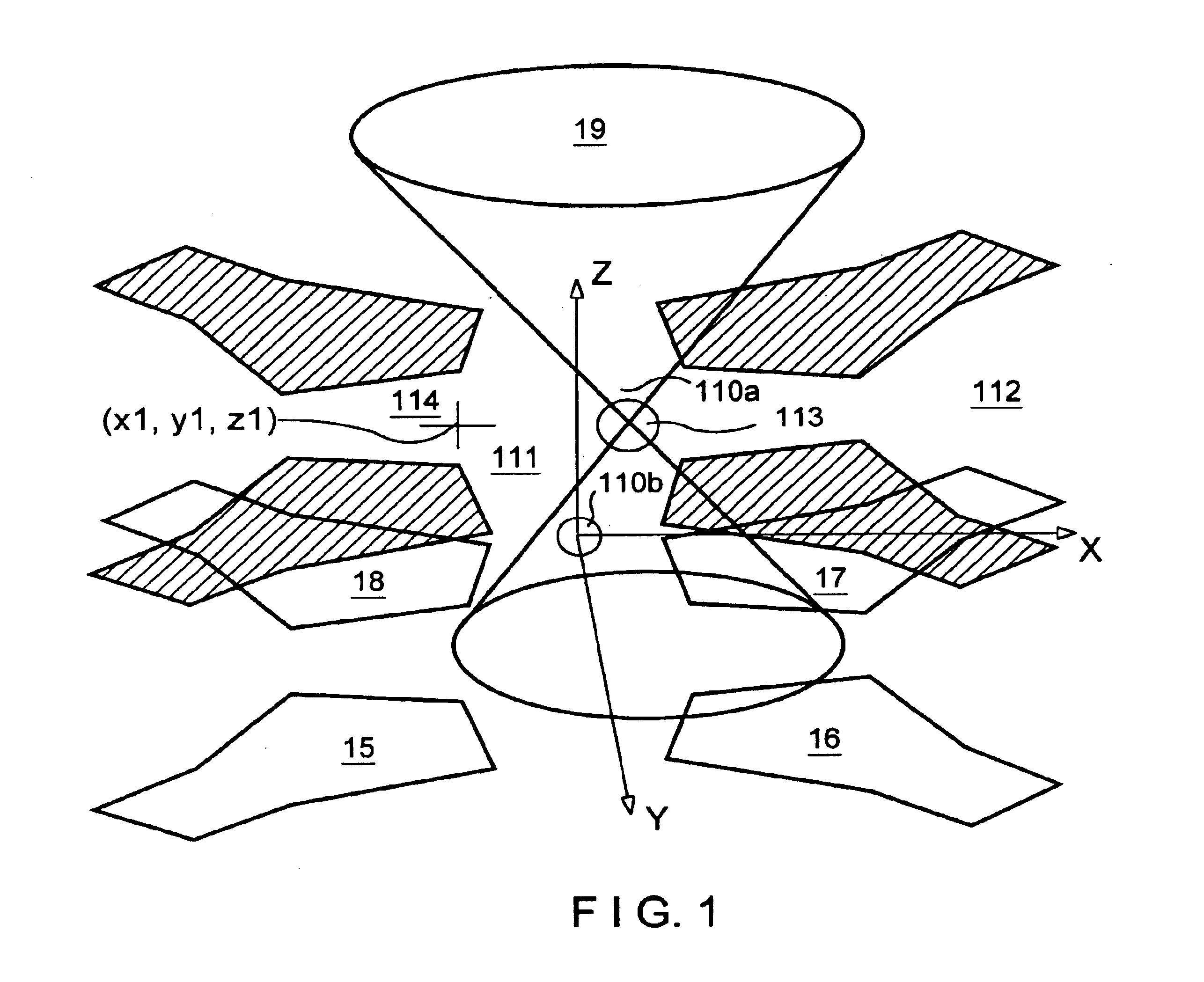
[0045]FIG. 1 schematically illustrates an enlarged section of a microsystem according to the invention. The diagram only shows a microelectrode arrangement consisting of the microelectrodes 11-18 (without control lines) and a microscopic particle 113 between the microelectrodes in a suspension liquid. The microelectrodes are flat on opposing walls of the microsystem structure, and e.g. the x-y plane coincides with a substrate plane. The microelectrodes 11-18 are set up to be supplied with electrical potentials to form field gradients with one minimum field level. The technology of the electrode control to generate a specific minimum level is known per se and will therefore not be described in detail. The pos...


PUM

PropertyMeasurementUnit
sizeaaaaaaaaaa
focal lengthaaaaaaaaaa
sizesaaaaaaaaaa

Abstract

To measure or exert optically-induced forces on at least one particle in the focus of an optical cage, the following steps are taken:
    • a) the focus is positioned in a microelectrode arrangement with a three-dimensional electrical field that has a field gradient which forms an electrical capture area, and the focus is at a distance from the capture are and
    • b) the amplitude of the electrical field, the light power of the light beam forming the optical cage, and/or the distance of the capture area from the focus are varied to detect which varied field property moves the particle from the focus to the capture area or vice versa, or at least to temporarily move the particle into the capture area.

Description

[0001]This application is a 371 of PCT / EP98 / 08370 filed on Dec. 21, 1998.[0002]The invention concerns processes and devices to measure and calibrate optical fields traps, determine optically-induced force in all three dimensions that are exerted on micrometer-sized particles, and to use optical field traps.BACKGROUND OF THE INVENTION[0003]Optical field traps, also called “optical tweezers”, “laser tweezers” or “optical traps” have been used for approximately two decades in the fields of biotechnology, medicine and molecular biology as well and other technical fields to position and manipulate micrometer-sized and submicrometer-sized particles (G. Weber et al. in Int. Rev. Cytol., Vol. 131, 1992, p. 1; S. M. Block in Noninvasive Techniques in Cell Biology, Wiley-Liss., New York 1990, p. 375). A. Ashkin has primarily started the development of laser tweezers (A. Ashkin in Phys. Rev. Lett., Vol. 24, 1970, p. 156). The principal of capturing particles by optically-induced forces is base...

Claims


Application Information

Patent Timeline
Patent Type & Authority Patents(United States)
IPC IPC(8): G01N33/53G01N33/543B81C99/00G21K1/00H05H3/04
CPCH05H3/04G21K1/006
Inventor FUHR, GUNTERSCHNELLE, THOMASMULLER, TORSTENHITZLER, HERMINEGREULICH, KARL-OTTOMONAJEMBASHI, SHAMOI
Owner EVOTEC BIOSYST
Why Eureka
Try Eureka