Q-switched oscillator seed-source for MOPA laser illuminator method and apparatus

a laser illuminator and oscillator technology, applied in the field of optical waveguides, to achieve the effect of wide dynamic range, increased optical pulse amplitude, and relatively slow amplification

Active Publication Date: 2011-05-26
LOCKHEED MARTIN CORP
View PDF56 Cites 71 Cited by
  • Summary
  • Abstract
  • Description
  • Claims
  • Application Information

AI Technical Summary

Benefits of technology

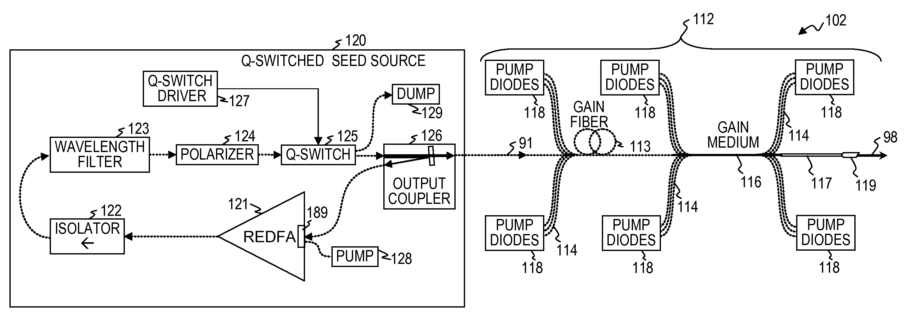
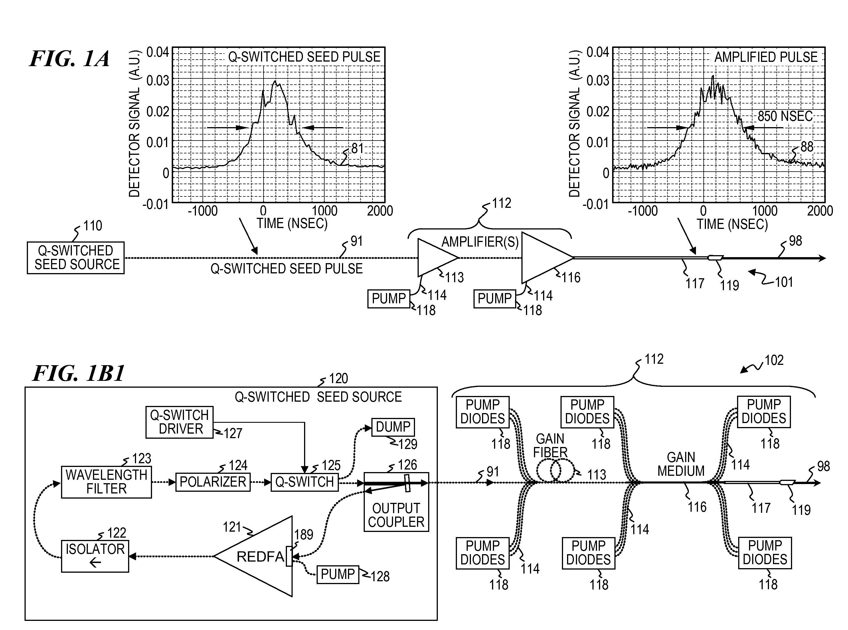
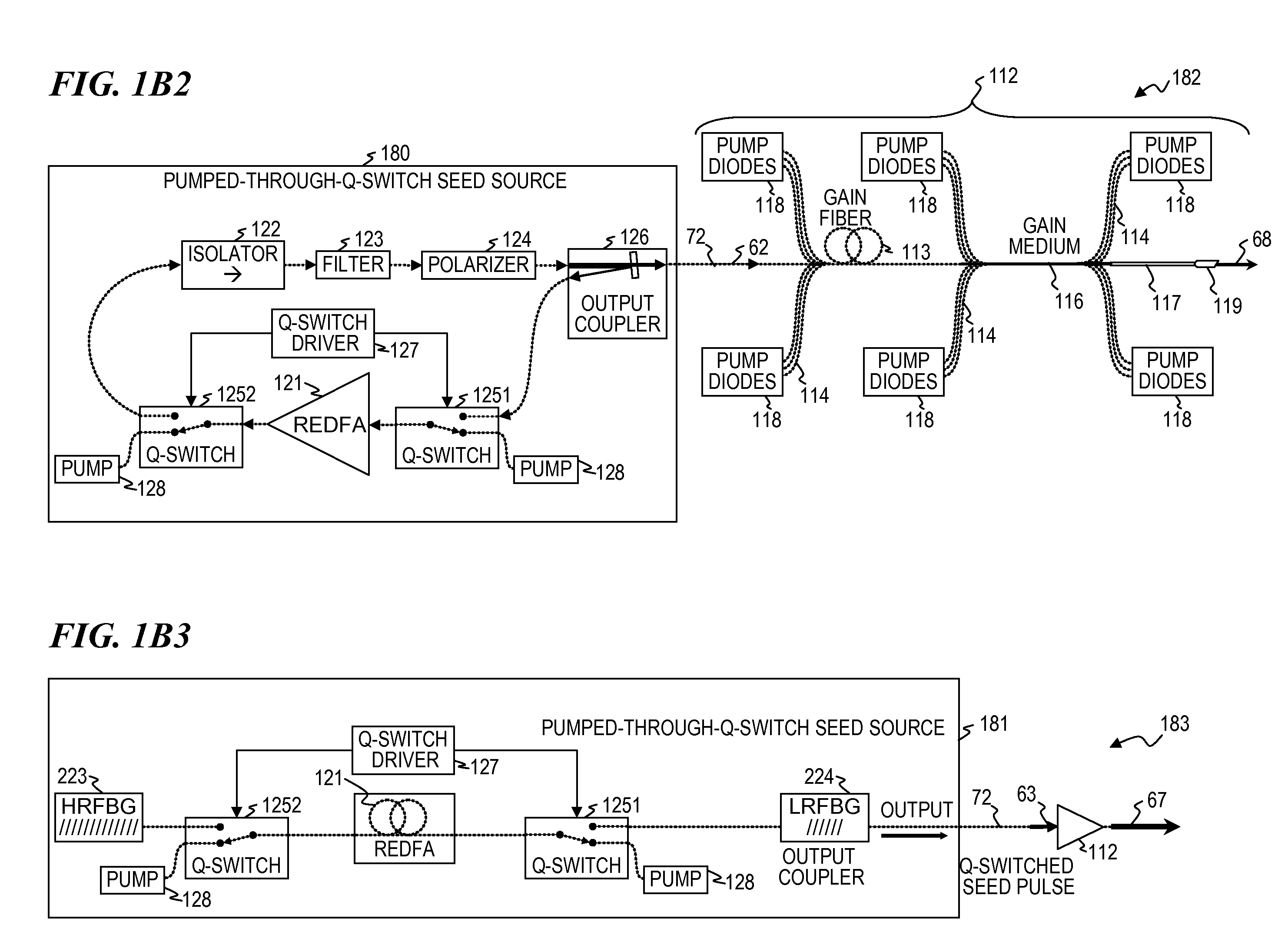
[0045]In some embodiments, the present invention provides an apparatus, method and system that uses a Q-switched laser as a seed source having a controlled high-dynamic-range amplitude that avoids and / or compensates for pulse steepening in high-gain optical-fiber amplification of long-duration laser pulses. In some embodiments, the output is used for illumination purposes (e.g., illuminating a scene for image acquisition). In some embodiments, well-controlled pulse shapes are obtained having a wide dynamic range, long duration, and not-too-narrow linewidth. In some embodiments, upon the opening of a Q-switch in an optical cavity having a gain medium, the amplification builds relatively slowly, wherein each round trip through the gain medium increases the amplitude of the optical pulse. This configuration results in an optical pulse having a very wide dynamic (i.e., very low amplitude after one round trip and a relatively slow and controlled increase in amplitude over time as the light passes again and again through the gain medium).

Problems solved by technology

In other embodiments, the Q-switch is configured as a variable-transparency semiconductor element, wherein a Q-switch driver circuit supplies sufficient electrical power to make the semiconductor transparent to allow lasing when the Q-switch is “on” and does not supply sufficient electrical power for transparency to allow lasing when the Q-switch is “off”, and in some such embodiments, this same semiconductor element also provides additional optical gain when sufficient electrical power is applied.

Method used


Image

  • Q-switched oscillator seed-source for MOPA laser illuminator method and apparatus
  • Q-switched oscillator seed-source for MOPA laser illuminator method and apparatus
  • Q-switched oscillator seed-source for MOPA laser illuminator method and apparatus

Examples


Embodiment Construction

[0095]Although the following detailed description contains many specifics for the purpose of illustration, a person of ordinary skill in the art will appreciate that many variations and alterations to the following details are within the scope of the invention. Accordingly, the following preferred embodiments of the invention are set forth without any loss of generality to, and without imposing limitations upon the claimed invention. Further, in the following detailed description of the preferred embodiments, reference is made to the accompanying drawings that form a part hereof, and in which are shown by way of illustration specific embodiments in which the invention may be practiced. It is understood that other embodiments may be utilized and structural changes may be made without departing from the scope of the present invention.

[0096]The leading digit(s) of reference numbers appearing in the Figures generally corresponds to the Figure number in which that component is first intr...


PUM


Abstract

An apparatus, method and system that uses a Q-switched laser or a Q-seed source for a seed pulse signal having a controlled high-dynamic-range amplitude that avoids and/or compensates for pulse steepening in high-gain optical-fiber and/or optical-rod amplification of optical pulses. Optionally, the optical output is used for LIDAR or illumination purposes (e.g., for image acquisition). In some embodiments, well-controlled pulse shapes are obtained having a wide dynamic range, long duration, and not-too-narrow linewidth. In some embodiments, upon the opening of a Q-switch in an optical cavity having a gain medium, the amplification builds relatively slowly, wherein each round trip through the gain medium increases the amplitude of the optical pulse. Other embodiments use quasi-Q-switch devices or a plurality of amplitude modulators to obtain Q-seed pulses. These configurations provide optical pulses having wide dynamic ranges that ameliorate problems of pulse steepening, non-linear spectral broadening and the like in very-high-power MOPA devices.

Description

CROSS-REFERENCE TO RELATED APPLICATIONS[0001]This application claims priority benefit under 35 U.S.C. §119(e) to U.S. Provisional Patent Application No. 61 / 263,736 filed on Nov. 23, 2009 by Matthias P. Savage-Leuchs et al., titled “Q-SWITCHED OSCILLATOR SEED-SOURCE FOR MOPA LASER ILLUMINATOR METHOD AND APPARATUS” (Attorney Docket AK10906.051PV1), which is incorporated herein by reference in its entirety.[0002]This invention is related to:[0003]U.S. Provisional Patent Application 61 / 343,947 filed Apr. 12, 2010 by Matthias P. Savage-Leuchs titled “HIGH-POWER LASER SYSTEM HAVING DELIVERY FIBER WITH NON-CIRCULAR CROSS SECTION FOR ISOLATION AGAINST BACK REFLECTIONS” (Attorney Docket 5032.052PV1);[0004]U.S. Provisional Patent Application 61 / 343,948 filed Apr. 12, 2010 by Matthias P. Savage-Leuchs titled “HIGH BEAM QUALITY AND HIGH AVERAGE POWER FROM LARGE-CORE-SIZE OPTICAL-FIBER AMPLIFIERS; SIGNAL AND PUMP MODE-FIELD ADAPTOR FOR DOUBLE-CLAD FIBERS AND ASSOCIATED METHOD” (Attorney Docket 5...

Claims


Application Information

Patent Timeline
Patent Type & Authority Applications(United States)
IPC IPC(8): H01S3/11
CPCH01S3/06712H01S3/0675H01S3/06758H01S3/06791H01S3/094011H01S3/094053H01S3/1022H01S3/115H01S3/127H01S3/2316H01S5/146H01S2301/03H01S3/06704H01S3/113B60Q1/0076H01S3/06716H01S3/094003H01S3/0941
Inventor SAVAGE-LEUCHS, MATTHIAS P.DILLEY, CHRISTIAN E.LEMAIRE, CHARLES A.
Owner LOCKHEED MARTIN CORP
Why Eureka
Try Eureka