Visual display with increased field of view

a visual display and field of view technology, applied in the field of image display and display system, can solve the problems of requiring redundancy of both systems, increasing circuitry and data load of any associated computer processing system, and achieving the effect of high resolution, lower resolution, and high resolution

Active Publication Date: 2009-02-24
RES TRIANGLE INST
View PDF22 Cites 67 Cited by
  • Summary
  • Abstract
  • Description
  • Claims
  • Application Information

AI Technical Summary

Benefits of technology

[0011]The non-uniform pixel spacing required to create the foveated images presented on a curved display is provided by an image source. An image source according to the present invention may consist of several variations of lenses and radiation sensors in order to provide a hardware-based, or hard-wired, foveated viewing. The present invention refers to hardware-based as the process of directly providing foveated images to the image display from the image source without the need for an intermediate step of image interpolation. This advantage of the present invention may be employed to drastically reduce the load and bandwidth on any associated computer system. Ideally, the non-uniform radius of curvature of a lens of an image source or the non-uniform resolution of a radiation sensor and the pixel density of the image display would match the visual acuity of the human eye. By recording foveated imagery and displaying corresponding foveated imagery, the present invention is able to provide foveated viewing using specific adaptations of hardware rather than relying upon additional processing of image interpolation.
[0012]In one advantageous embodiment of the invention an anamorphic lens can distort the incoming image onto a linear radiation sensor. The linear radiation sensor may be a camera with a linear lens. This type of image source system would be ideal for using a continuous, curved visual display or panel array. Another embodiment of the present invention uses two anamorphic lenses each providing foveated view for a single eye. The right anamorphic lens providing imaging for the right eye would provide higher resolution at the central region of the relaxed forward gaze of the right eye and lower resolution at the periphery of the right eye. Similarly, the left anamorphic lens would provide high resolution for the relaxed forward gaze of the left eye and low resolution in the periphery of the left eye. In order to provide the non-uniform resolution imagery, these anamorphic lenses may be aspherical and may have non-uniform curvature across the surface.
[0013]Another advantageous embodiment of the hardware-based foveated viewing would include linear lenses and anamorphic sensors. This embodiment would require continuous anamorphic sensors without dead zones or areas within the sensor which do not record radiation information. This continuous aspect of the sensors is required to provide a full image on a continuous display of varying pixel sizes.
[0014]The displays of the present invention can also be used when using linear lenses and sensors and an image processor that includes an image interpolator that transforms the linear image into a variable acuity image that can be displayed on the single or dual continuous displays or arrays. A fixed or hard-coded interpolation scheme may also be used. Many variations of lenses and sensors or cameras can be employed using an image interpolator. For example, a lens and sensor can be used in coordination with a single display device. Two linear lenses and radiation sensors can be used for dual continuous display devices. To further reduce the load on the image processor by reducing the image data bandwidth, multiple cameras of higher and lower resolution can be used to input the source image in the central or periphery regions of the display. For example, four low resolution cameras can be used to generate the source image periphery and one or two high resolution cameras can be used to generate the central region. To further reduce the image data bandwidth and processor load, anamorphic lenses or anamorphic sensors can be used in dual input formats where high resolution and low resolution input sources are used to create the source image.
[0015]The present invention may include additional input sources for infrared (IR) or ultraviolet (UV) radiation, or the existing input devices can be adjusted to accept more than wavelengths in the visual spectrum. Also, the image processor may include a merge module to merge or fuse two different image sources together into a final image that will be displayed on the single or dual continuous display or arrays. Additionally, the image processor may include a gain module to improve low-light viewing or a clipping module to limit high amplitudes of light that may damage the human eye.
[0016]Each of these embodiments is intended to eliminate the redundancy of high resolution images being overlaid onto low resolution images to create a synthesized foveated image. The single or dual continuous displays are intended to eliminate the need for an optical viewing system rather than a non-uniform, pixelated viewing system. The curvature of the displays or arrays is intended to limit the severe angle between a viewer's eyes and the peripheral images on the display.

Problems solved by technology

However, each of these visual display systems suffer from a reliance upon a redundancy of image information being presented to the viewer or the computer system.
The redundancy of both of these systems requires increased circuitry and a higher data load on any associated computer processing system.
An additional disadvantage of primarily ocular systems is the substantial complexity, size, and weight of the components required for such a system.
Furthermore, existing near-eye visual displays that rely upon optical projection systems or flat computer generated displays often cause discomfort for the viewer because they fail to accommodate the severe angle between the eyes and peripheral images on the display.
A disadvantage of the Yamazaki '007 patent is the need to adjust the pixel width on existing flat panel visual displays, requiring an additional step of software image interpolation.
Furthermore, existing near-eye displays have substantial disadvantages including excessive and awkward weight and small viewing screens.

Method used


Image

  • Visual display with increased field of view
  • Visual display with increased field of view
  • Visual display with increased field of view

Examples


Embodiment Construction

[0036]The present inventions now will be described more fully hereinafter with reference to the accompanying drawings, in which some, but not all embodiments of the invention are shown. Indeed, these inventions may be embodied in many different forms and should not be construed as limited to the embodiments set forth herein; rather, these embodiments are provided so that this disclosure will satisfy applicable legal requirements. Like numbers refer to like elements throughout.

[0037]While a primary use of the present invention is in the field of image display systems, it will be appreciated from the following description that the invention is also useful for many types of near-eye and remote optical image displays with non-uniform resolutions.

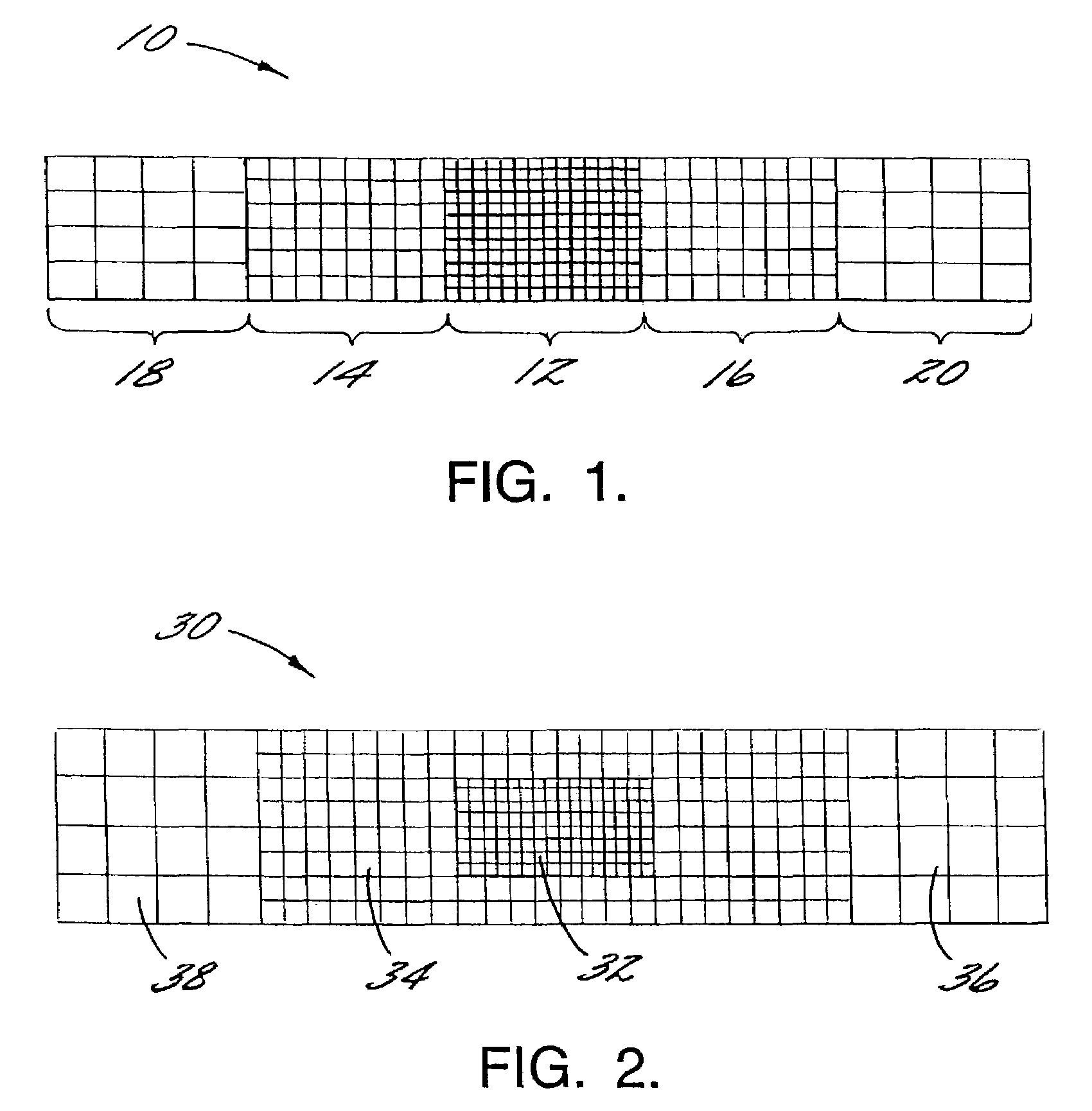
[0038]FIG. 1 shows a continuous display with non-uniform pixel density 10. The central region of the display 12 is capable of displaying the highest resolution image because it has a higher density of pixels than the other regions of the display...


PUM


Abstract

This invention provides a continuous display with non-uniform pixel density, forming a foveated display. A single, continuous display has a higher pixel density at the center of the display than at the periphery of the display. Where two continuous displays are used in accordance with the present invention, the central forward gaze of the viewer's image will be displayed in high resolution while the leftmost portion of the left eye display will be in low resolution and the rightmost portion of the right eye display will be in low resolution. The pixel resolution of the visual display may correspond to the visual acuity of the human eye. A foveated image display system using a continuous display with non-uniform pixel density increases the field of view while reducing the image bandwidth. A foveated image display system may be hardware-based by employing anamorphic lenses or sensors rather than relying upon image interpolation to modify the resolution of the resultant image data communicated to the continuous display with non-uniform pixel density.

Description

FEDERALLY SPONSORED RESEARCH OR DEVELOPMENT[0001]The U.S. Government may have certain rights in the present invention as provided by the terms of Contract Numbers DAAD19-00-2-0003 and DAAD19-00-2-0003 awarded by the United States Army.FIELD OF THE INVENTION[0002]The present invention relates generally to image displays and display systems, and, more particularly, to near-eye optical image displays and display systems with varying resolutions for foveated viewing.BACKGROUND OF THE INVENTION[0003]The human eye provides a foveal characteristic of vision. The central region of the retina, the fovea, is capable of interpreting higher resolution imagery, greater detail, than surrounding regions of the retina. Visual acuity of the retina falls off further from the fovea, as the foveal angle increases. Consequently, the human eye resolves high resolution at the center of the field of view and continually decreasing resolution at greater peripheral areas of the field of view. This high-resol...

Claims


Application Information

Patent Timeline
Patent Type & Authority Patents(United States)
IPC IPC(8): G09G3/30G02B27/00G02B27/01H04N5/74
CPCG02B27/0172G02B2027/0132G02B2027/014H04N5/7491G09G3/3233G09G2300/0842G09G2340/0407
Inventor LAMVIK, MICHAEL K.MCGUIRE, GARY E.LEWIS, III, JOHN S.
Owner RES TRIANGLE INST
Why Eureka
Try Eureka