
Operating solid-state lighting elements

a technology of solid-state lighting and lighting elements, which is applied in the direction of electric variable regulation, process and machine control, instruments, etc., can solve the problems of dimming of solid-state light sources without accounting for their thermal constraints, and efficient lumen output, so as to reduce the brightness level of solid-state light sources, reduce the effect of luminous efficacy and efficiency

Inactive Publication Date: 2009-06-25
KONINKLIJKE PHILIPS ELECTRONICS NV
View PDF3 Cites 72 Cited by
  • Summary
  • Abstract
  • Description
  • Claims
  • Application Information

AI Technical Summary

Benefits of technology

[0006]It is an object of the present invention to realize efficient use of solid-state light sources. It is a further object of the present invention to ensure an increased luminous efficacy and efficiency, while dimming the brightness level of solid-state light sources. It is another object of the present invention to provide optimum luminous efficacy and efficiency at a given brightness level, and driving the solid-state lighting unit with the reference driving current amplitude when the reference driving current amplitude is larger than the optimum driving current amplitude.
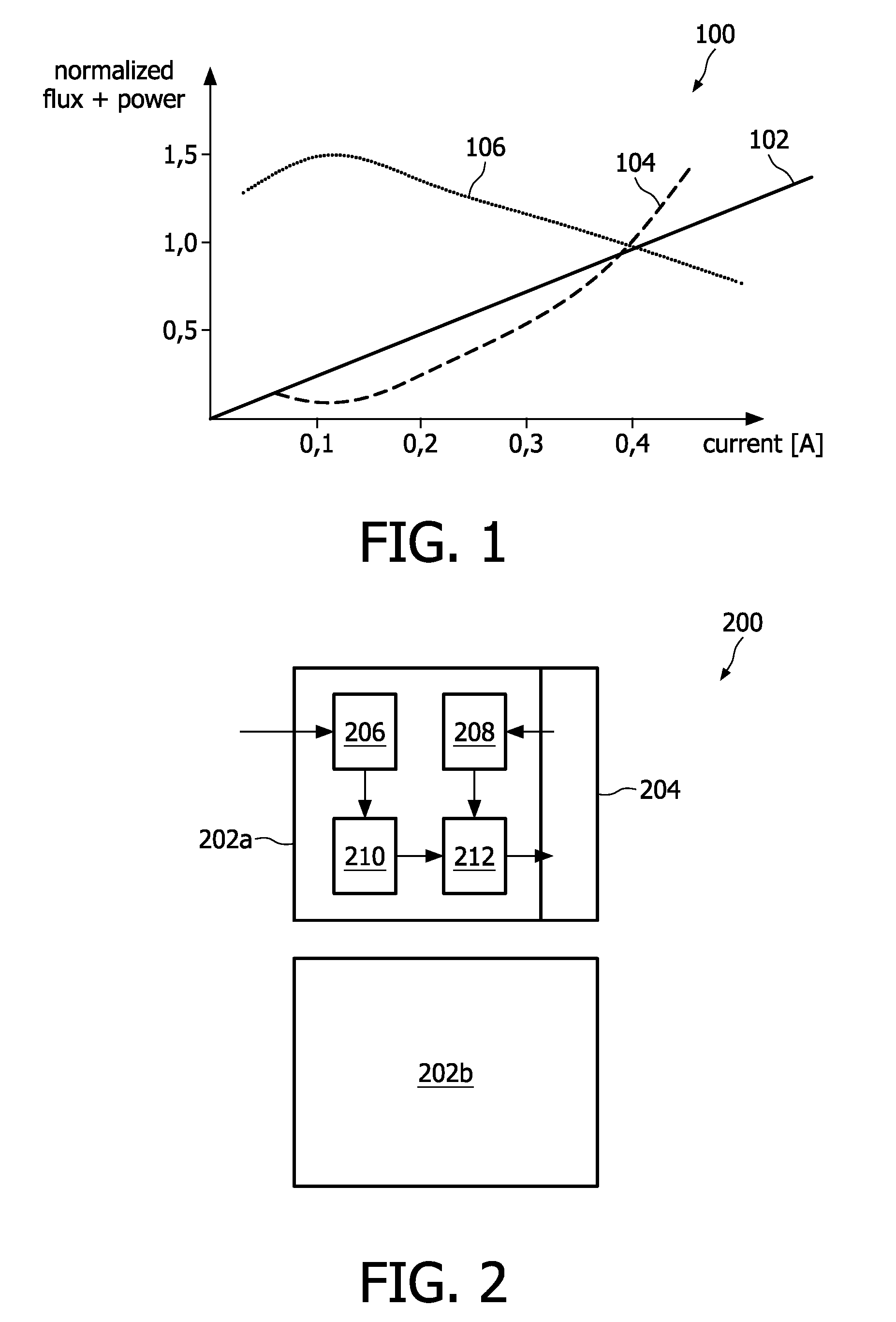
[0008]It has been found that, whilst lumen output is largest at the maximally allowable current amplitude, the luminous efficacy and efficiency are larger at smaller current amplitudes. An optimum driving current amplitude may be obtained by evaluating operational data of the solid-state lighting units, such as the relative luminous flux and electric input power curves of the data sheets. It has further been found that a target brightness level may be obtained by driving a solid-state lighting unit with an optimum driving current amplitude and by pulse-width modulating this optimum driving current amplitude. This accounts for obtaining the maximum efficiency of the solid-state lighting unit.
[0009]According to the present invention, the intensity of solid-state lighting units, such as LEDs used in LED lamps, as well as the intensity of a plurality of LEDs, can be manipulated, while still providing a high efficiency. Changing the color and increasing the brightness difference between LEDs of the same color can be controlled, while maintaining a high efficiency.
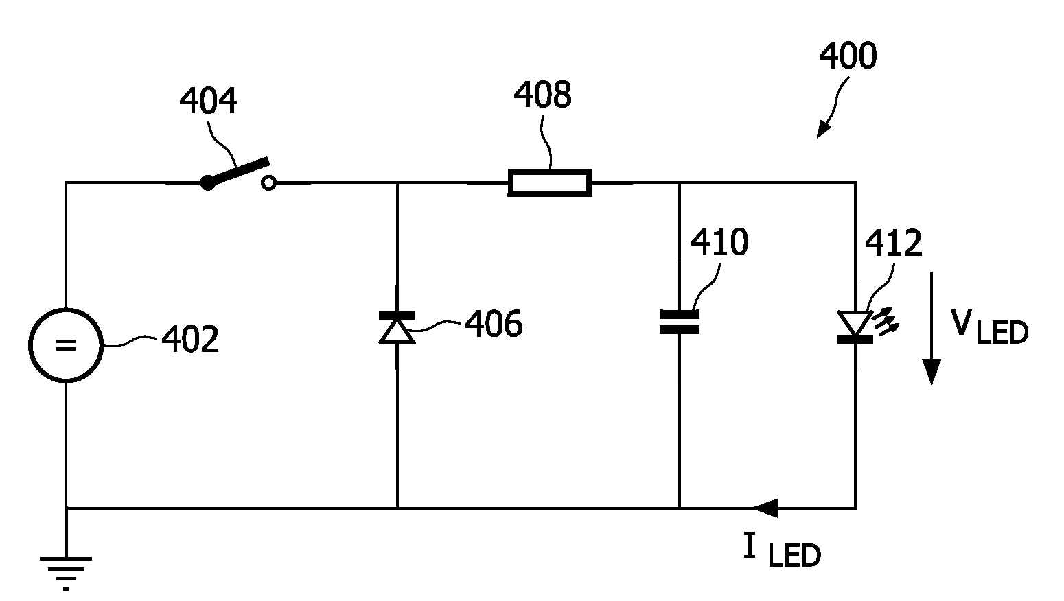
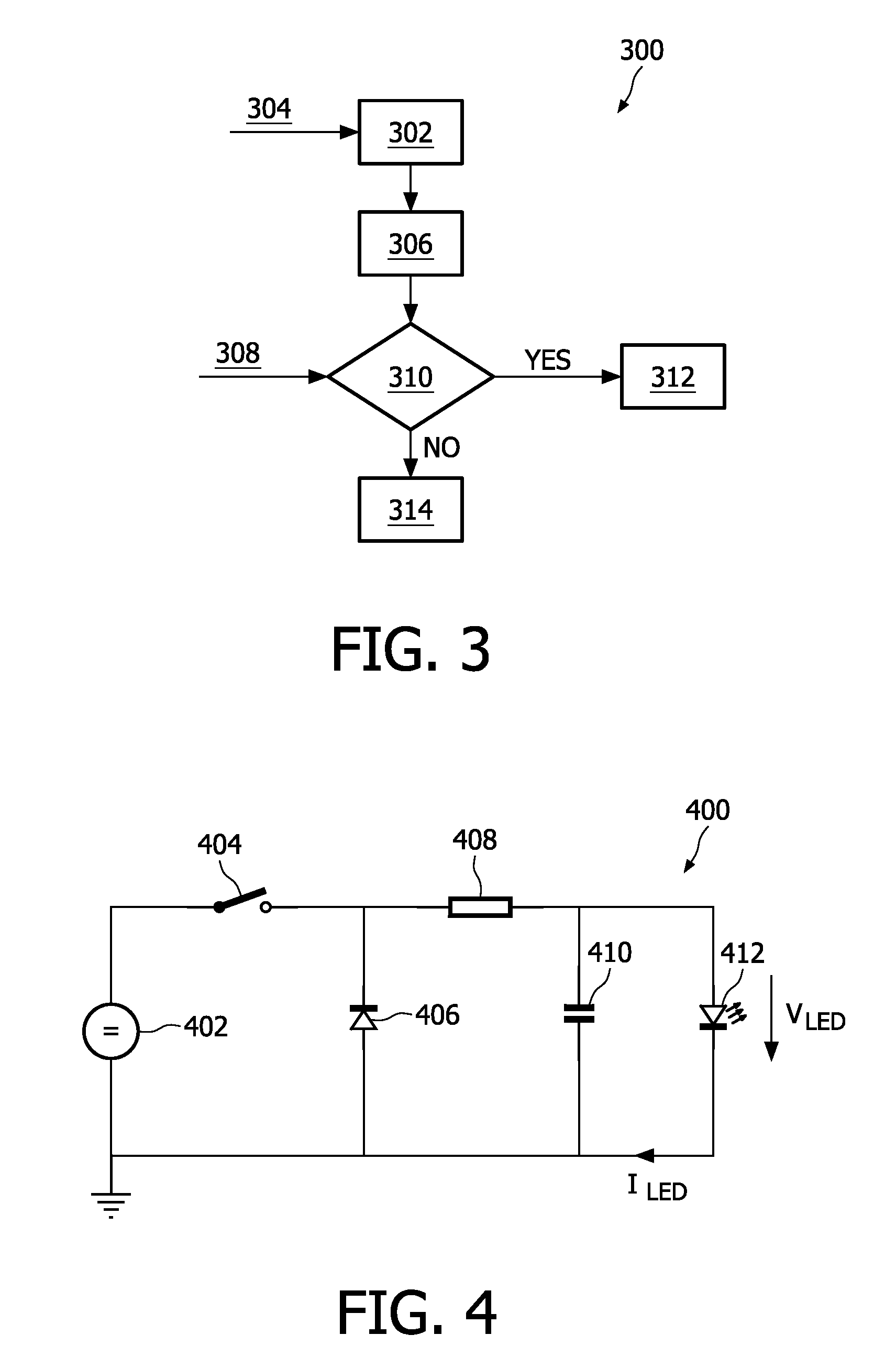
[0013]If the reference driving current is smaller than or equal to the optimum driving current, the present invention ensures that the solid-state lighting unit is driven with the optimum driving current amplitude, which is pulse-width modulated. The optimum driving current amplitude, if applied to the solid-state lighting unit without any further modulation, will thus provide a brightness level which is higher than the target brightness level. Nevertheless, the optimum driving current amplitude provides the maximum efficiency for the solid-state lighting unit. To obtain the target brightness level, it is proposed to pulse-width modulate the optimum driving current amplitude. This pulse-width modulation accounts for dimming the brightness level until the target brightness level is obtained.
[0022]A further aspect of the invention is a system comprising at least two lighting devices, as previously described. The two lighting devices are driven by a driving unit in accordance with a method as previously described. This system ensures operation of solid-state lighting systems with more than one solid-state lighting source. It may provide adaptation of the overall brightness level of the lamps to the ambient light. Furthermore, it is possible to control the brightness level of single solid-state lighting units in order to adjust the lamp color and overall brightness.
[0024]These aspects of the invention lead to an optimum luminous efficacy and efficiency at a given brightness level, and to driving the solid-state lighting unit with the reference driving current amplitude when the reference driving current amplitude is larger than the optimum driving current amplitude.

Problems solved by technology

This may be accompanied by thermal constraints.
However, driving the solid-state light sources with the maximal driving current does not result in an efficient lumen output, i.e. the luminous efficacy may be higher at lower driving currents.
However, this leads to dimming of the solid-state light sources without accounting for their luminous efficacy and efficiency.

Method used


Image

  • Operating solid-state lighting elements
  • Operating solid-state lighting elements
  • Operating solid-state lighting elements

Examples


Embodiment Construction

[0033]The present invention ensures an increase of the luminous efficacy for solid-state light sources, even at low brightness levels. The use of amplitude modulation to dim the brightness level of the solid-state light sources is suggested in monochrome lamps as well as in multi-color lamps, such as RGB LED lamps. This amplitude modulation is applied until the luminous efficacy is maximum. It is further proposed to keep the current amplitude at this value and use pulse-width modulation for dimming the brightness level to lower values. Using the inventive method allows dimming of solid-state lighting units with an optimized luminous efficacy in both monochrome and colored solid-state light sources.

[0034]The method and device according to the invention utilize the fact that the luminous efficacy and the efficiency of the luminous flux of a solid-state lighting unit depends on the driving power and the luminous flux of the lighting unit. FIG. 1 is a chart 100 illustrating the dependen...


PUM


Abstract

Operating a lighting device by acquiring a target brightness level of at least one solid-state lighting unit, and determining a reference driving current amplitude for obtaining the target brightness level. If the reference driving current amplitude is below an optimum driving current amplitude, the solid-state lighting unit is operated at the optimum driving current amplitude, which is pulse-width modulated to obtain the target brightness level.

Description

FIELD OF THE INVENTION[0001]The present invention relates in general to solid-state lighting and methods of operating solid-state lighting units.BACKGROUND OF THE INVENTION[0002]Solid-state lighting has become an important feature in the illumination market. Solid-state lighting (SSL) units, such as light-emitting diodes (LED), and organic light-emitting diodes (OLED), provide lighting at low cost, and are therefore intended for the general illumination market. The solid-state light sources provide light at certain wavelengths. The wavelengths are dependent on the materials used, i.e. semiconductors, and environmental properties of the SSL units. Furthermore, the solid-state light sources may have a high luminous efficacy, but this is also a function of temperature and driving method.[0003]In current lighting applications, the lumen output of the solid-state light sources is desired to be at a maximum. The solid-state light sources are therefore driven with a current at the maximall...

Claims


Application Information

Patent Timeline
Patent Type & Authority Applications(United States)
IPC IPC(8): H05B37/02H05B44/00
CPCH05B33/0848H05B33/0818H05B45/14H05B45/375
Inventor ACKERMANN, BERNDHENTE, DIRKMARTINY, CHRISTOPHSAUERLANDER, GEORGWENDT, MATTHIAS
Owner KONINKLIJKE PHILIPS ELECTRONICS NV
Learn More