High Resolution Projection Micro Stereolithography System And Method

a projection system and stereolithography technology, applied in the field of projection micro stereolithography systems and methods, can solve the problems of limiting the practical number of layers possible, affecting the quality of the material, and the type of resin available for this technique is severely limited, so as to achieve uniform delivery and distribution of materials, enhance the introduction of different types of materials into the bath vessel, and ensure the effect of quality

Active Publication Date: 2015-10-29
LAWRENCE LIVERMORE NAT SECURITY LLC
View PDF3 Cites 70 Cited by
  • Summary
  • Abstract
  • Description
  • Claims
  • Application Information

AI Technical Summary

Benefits of technology

[0011]Another aspect of the present invention includes a holographic projection micro-stereolithography (PμSL) system, comprising: a stereolithographic bath containing a photosensitive resin; and at least two light projection systems, each projection system comprising a light source; and a spatial light modulator (SLM) illuminated by the light source for illuminating the photosensitive resin with a digital image, so that the holographic interference of all the digital images in the photosensitive resin cures select regions of the photosensitive resin.
[0014]The FLS takes the form of a thin layer of material with either negative permittivity or permeability (resulting in a negative index of refraction). Noble metals such as silver are good candidate materials for the FLS due to the ability to generate negative permittivity by the collective excitation of conduction electrons. The thin metal grating layer is designed such that the surface plasmons match the evanescent waves being imaged so that the FLS enhances the amplitude of the field. Features as small as 5 μm for example have been demonstrated.
[0017]It is appreciated that the metallic grating layer may also be formed as a multilayer comprising several thin film layers of other materials, such as for example the combination of silver / MgO / silver composite (or silver, Al2O3, silver) which could serve as a superlens for wavelength of 500 nm. Such metal composite / multilayers may enable operation of the FSL at other wavelengths or simply may provide an alternative to silver in the UV range. The layers of the multilayer can consist of a seed or adhesion layer such as germanium or MgO. This is intended to provide smooth growth of metallic layer such as Ag or Au. There is also a composite layer made of metal and dielectrics, such as MgO / Ag / MgO / Ag . . . thin film stacks, or it can contain porous anodized Al2O3 or TiO2 with electroplated metal, such as Ag, Au, or conductive oxide fillers. The importance of the composite layer is to provide a impedance matching element for resonant transfer of evanescent waves. In addition, a layer is integrated to convert evanescent waves to far field. This can be implemented such as metallic grating or dynamic grating produced by photorefractive effect or electro-optical effects.
[0021]Another feature of the present invention is the integration of microfluidic components and sub-systems (in particular laminar flow systems) with the PμSL system to provide the capability of fabricating structures (such as 3D structures) with multiple, heterogeneous materials in the same component. By incorporating microfluidic systems into the resin bath of a PμSL system, the present invention has the ability to fabricate microstructures of different materials in one process. By slowly flowing layers of photosensitive resin a single exposure and curing step in one material can be completed. A new material (different resin or loading of metal / ceramic particles) can follow in another fluid layer. This material can then be exposed and cured resulting in a multilayer material. If the fluid is allowed to settle in void areas then multiple materials can be cured on the same image plane and concentric structures of different materials (such as double shelled targets) may be fabricated. Laminar flow microfluidic systems in particular provide for more uniform delivery and distribution of materials and to allow for multiple material components to be sequentially exposed.
[0022]Various types of materials (various photosensitive liquids or slurries with metal or ceramic nanoparticles) may be injected into the fabrication area through a single, valved, microfluidic channel and port allows for the ability to sequentially fabricate with different materials. For example, one material can flow into the fabrication zone and layers lithographically formed. This material then is removed via another microfluidic port while a new material flows into the fabrication zone. More features / layers may then be produced. The multiple materials could be in the same device layer or could form a layered structure. Furthermore, microfluidic integration may be implemented with multiple injection ports for various materials. These ports could be arranged around the fabrication area in almost any desired geometry including radially oriented or at different vertical positions. This would allow for more precise injection of different materials to specific locations in the fabrication zone. The injection could occur simultaneously or could be staged in time depending on the part to be fabricated. In general, this will allow for additional material and geometric flexibility in final fabricated part.
[0023]The introduction of different types of materials in to the bath vessel may be enhanced by enclosing the fabrication zone and liquid with a membrane cover. The membrane can be made of PDMS or any other relatively inert material; however it needs to have some gas permeability and be optically transparent. The membrane provides several advantages; 1) it dampens any disturbances on the free surface of the liquid monomer bath (this increase fabrication speeds) and 2) it creates a completely enclosed fluidic bath which results in smooth fluid flow around fabricated features. The membrane must be permeable so that there is a thin layer of gas between the membrane and the liquid otherwise fabricated features may stick to the membrane. The below figures show and schematic of how the membrane can be integrated into the PμSL system and some multimaterial parts fabricated with this technique.

Problems solved by technology

While the beams can write a completely three-dimensional pattern into the resin bath, this is typically a slow process because it writes in a point-by-point fashion.
Moreover, the types of resins available for this technique are severely limited due to the need that they be highly transparent to the laser beams, which also effectively prevents the loading of ceramic or metal particles in the resin bath.
Although effective, this method requires a large number of photomasks thus limiting the practical number of layers possible.
However, the LCD had some intrinsic drawbacks including large pixel sizes and low switching speeds.
It is also known that imaging and lithography using conventional optical components is restricted by the diffraction limit.
Features resolution in these systems is limited to one half of the wavelength of the incident light because they can only transmit the propagating components emanating from the source.

Method used


Image

  • High Resolution Projection Micro Stereolithography System And Method
  • High Resolution Projection Micro Stereolithography System And Method
  • High Resolution Projection Micro Stereolithography System And Method

Examples


Embodiment Construction

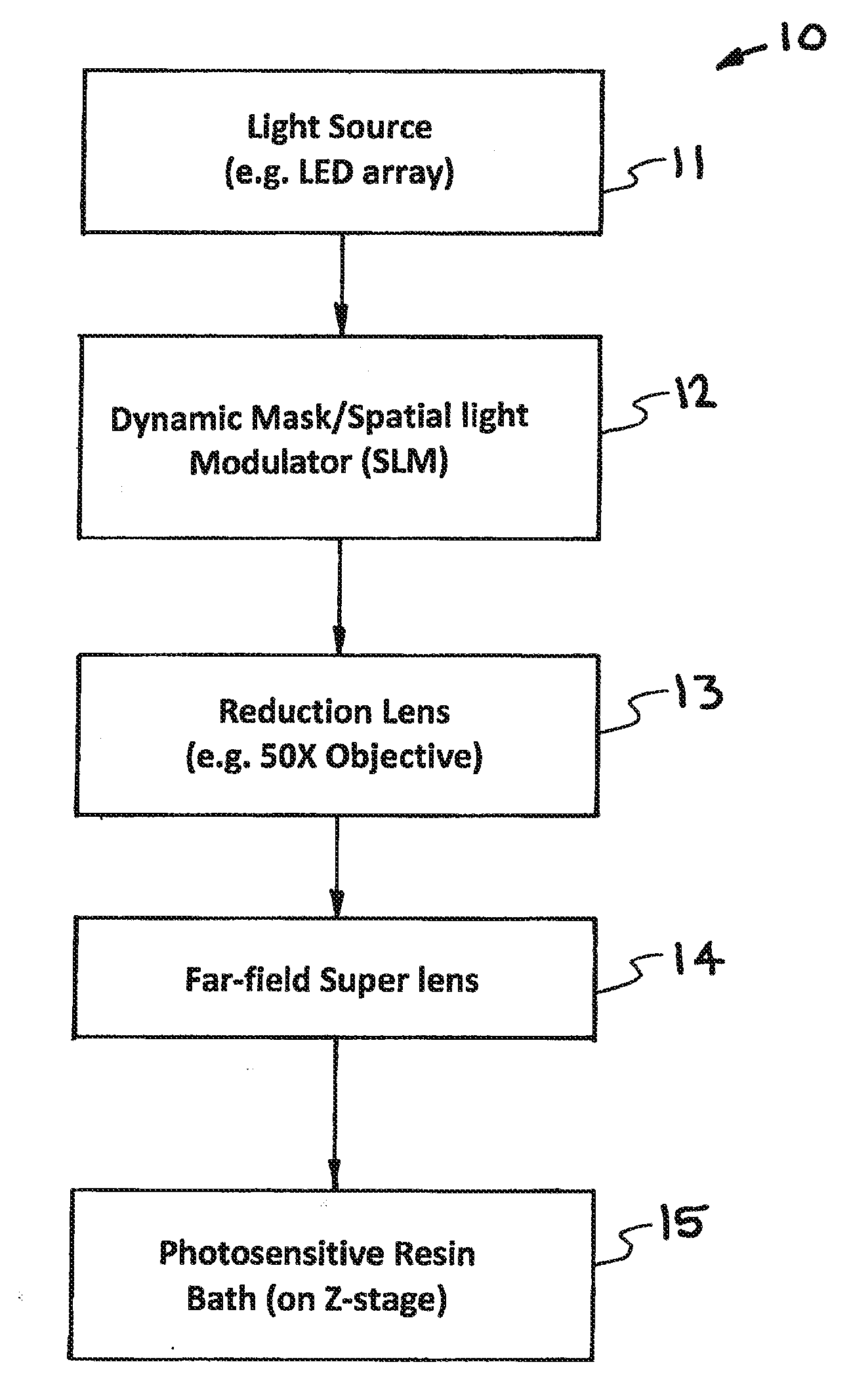
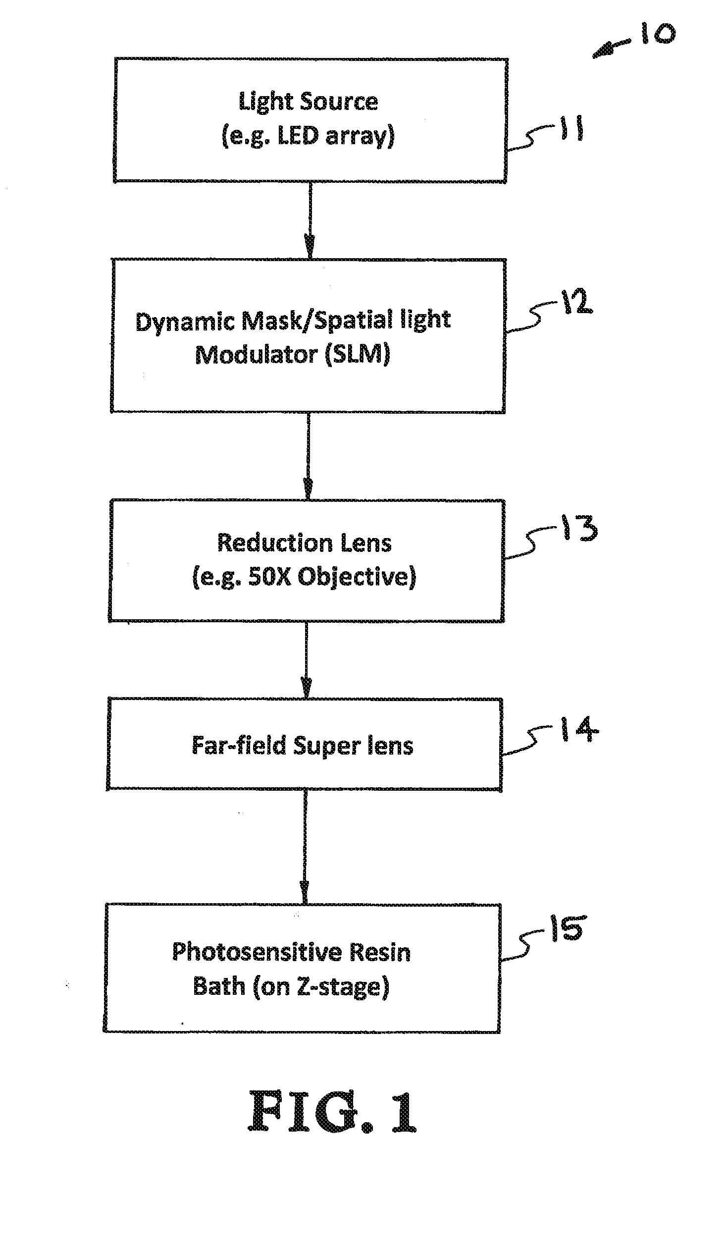
[0033]Turning now to the drawings, FIG. 1 shows a flow diagram generally illustrating the primary components and the optical path of a first exemplary embodiment of a PμSL system 10 of the present invention to produce three-dimensional structures (e.g. meso- or micro-scale) with sub-diffraction-limited features. As shown in FIG. 1, the system 10 generally includes a light source 11, such as for example a UV LED array, which produces electromagnetic radiation (hereinafter “light”) of a given wavelength, (e.g. 350 nm for UV). The system also includes a SLM 12 which functions as a dynamically configurable mask to produce a two-dimensional pattern / image from the light. The two dimensional image produced from the SLM 12 is then reduced by a reduction lens 13, and projected onto an FSL 14 which is positioned adjacent a photosensitive resin bath 14. The reduced two dimensional image from the SLM (i.e. far field image), is converted by the FSL 14 into a different two-dimensional image (i.e....


PUM

PropertyMeasurementUnit
thicknessaaaaaaaaaa
thicknessaaaaaaaaaa
thicknessaaaaaaaaaa

Abstract

A high-resolution PμSL system and method incorporating one or more of the following features with a standard PμSL system using a SLM projected digital image to form components in a stereolithographic bath: a far-field superlens for producing sub-diffraction-limited features, multiple spatial light modulators (SLM) to generate spatially-controlled three-dimensional interference holograms with nanoscale features, and the integration of microfluidic components into the resin bath of a PμSL system to fabricate microstructures of different materials.

Description

CROSS-REFERENCES TO RELATED APPLICATIONS[0001]This application claims the benefit of U.S. Provisional Application No. 61 / 349,627, filed May 28, 2010 and incorporated by reference herein.FEDERALLY SPONSORED RESEARCH OR DEVELOPMENT[0002]The United States Government has rights in this invention pursuant to Contract No. DE-AC52-07NA27344 between the United States Department of Energy and Lawrence Livermore National Security, LLC for the operation of Lawrence Livermore National Laboratory.FIELD OF THE INVENTION[0003]The present invention relates to projection micro-stereolithography (PμSL) systems and methods, and more particularly to an improved high-resolution PμSL system and method having one or more of the following features: a far-field superlens for producing sub-diffraction-limited features, multiple spatial light modulators (SLM) to generate spatially-controlled three-dimensional interference holograms with nanoscale features, and the integration of microfluidic components into t...

Claims


Application Information

Patent Timeline
Patent Type & Authority Applications(United States)
IPC IPC(8): G03H1/26G02B5/00B29C67/00G03H1/02G03H1/00G02B1/00G02B27/56
CPCG03H1/268G02B1/002G02B5/008G02B27/56G03H1/02G03H1/0005G03H2001/2695G03H2001/0094G03H2001/026B33Y30/00B33Y70/00B33Y10/00B29C67/0051B29C64/124B29C64/135G03F7/70408G03F7/70416G03H1/2294G03H2225/60G02B1/007G03H1/0476G03H2001/0482G03H2223/17
Inventor SPADACCINI, CHRISTOPHER M.FARQUAR, GEORGEWEISGRABER, TODDGEMBERLING, STEVENFANG, NICHOLASXU, JUNALONSO, MATTHEWLEE, HOWON
Owner LAWRENCE LIVERMORE NAT SECURITY LLC
Why Eureka
Try Eureka