
Compensation system and method for sound reproduction

a sound reproduction and compensation system technology, applied in the direction of digital signal tone/bandwidth control, electrical apparatus, amplification control, etc., can solve the problems of mechanical, acoustic properties of loudspeakers that are often less than ideal, response anomalies, other coloration of sound, etc., to improve the frequency, time, phase and amplitude performance of the device, improve sound clarity, and improve the effect of sonic balan

Inactive Publication Date: 2007-02-27
MICROSOFT TECH LICENSING LLC
View PDF20 Cites 73 Cited by
  • Summary
  • Abstract
  • Description
  • Claims
  • Application Information

AI Technical Summary

Benefits of technology

[0020]Briefly, and in general terms, the present invention provides a system and method for modeling individual response characteristics of a sonic reproduction device to create a conjugate model for improving frequency, time, phase, and amplitude performance of the device and to provide improved sonic balance, sound clarity, reduced distortion and improved stereo imaging.
[0033]These features and the ability to maintain sonic neutrality make a compensation system and method capable of complex, dynamically changing response corrections, which can be controlled and adjusted with simplified, intuitive control specifications. Compared to traditional response-leveling methods, the compensation method and system requires less processing complexity and can easily be applied to different sound-reproducing systems. The compensation method and system, as a whole or in piece parts, can be turned on or off, moved from one frequency to another, or otherwise be changed by simple, intuitive commands.

Problems solved by technology

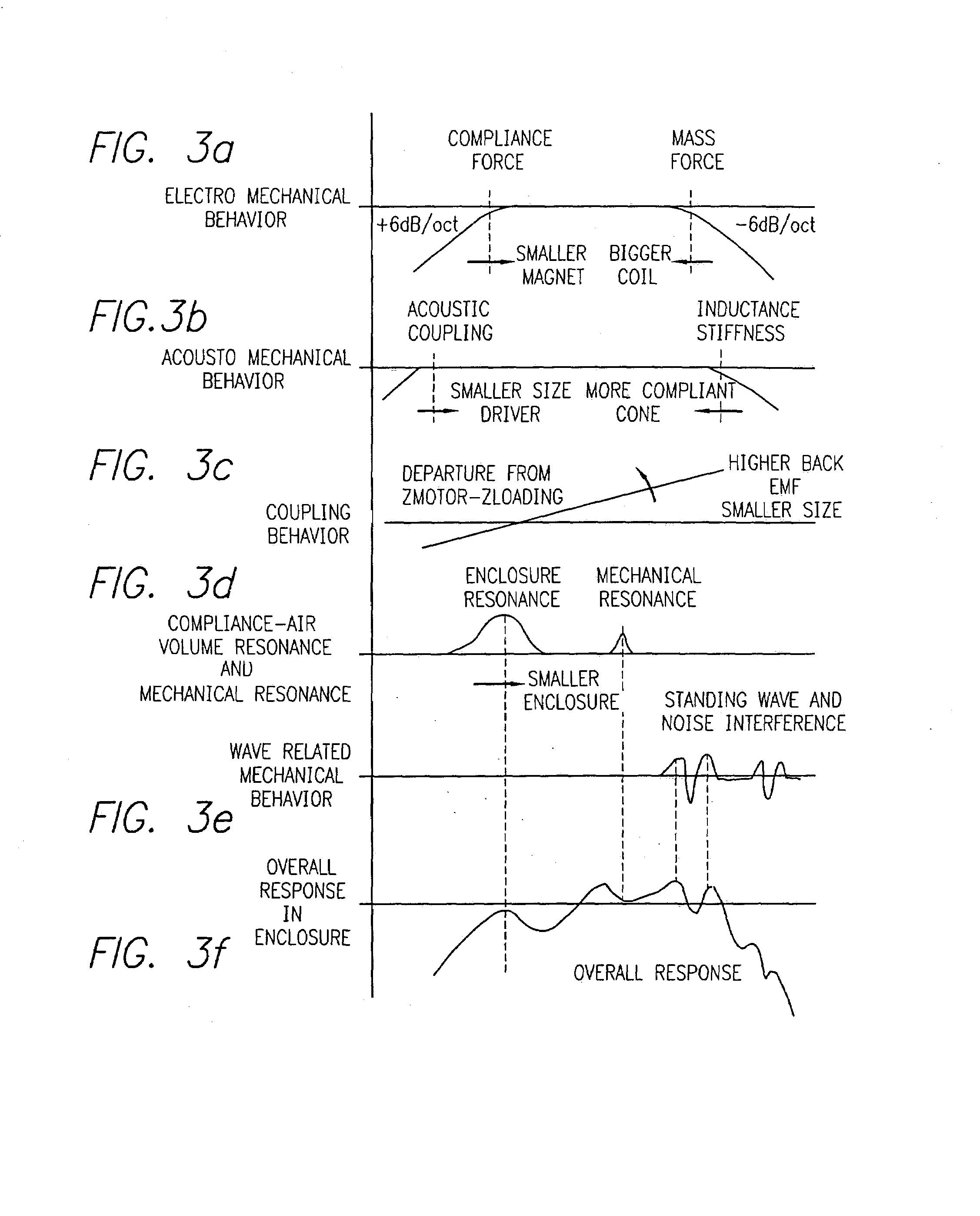
The electrical, mechanical, and acoustical properties of the loudspeakers are often less than ideal, causing distortions, response anomalies, and other coloration of the sound.
The model still responds like the speaker, but the parts making the model no longer have exact behavioral equivalence to the parts making the speaker.
Consequently, traditional models are neither intended, nor capable of making parametrically addressed zero-phase compensations when speaker parts are changed.
The technique does work to a fashion, but its dedicated, inflexible circuitry or specialized process tied to the traditional model limits its use to a one-speaker design.
When more corrections are added the interaction problem becomes formidable.
Analog methods are impractical and digital processes require much computation and extensive architectures to do this.
Without a model, the effort to combine amplitude, time and phase corrections together from measured responses becomes formidable.
Some of the most important behaviors of loudspeakers (with respect to acoustically perceptible effect) cannot be modeled or implemented from traditional methods.
Any of these can create source movements, delayed energy release, and phase error to binaural hearing.
Often, such destructive responses can be invisible or very difficult to interpret from traditional microphone-and-spectrum-analyzer calibration methods.
Frequently, these responses cause perceptual changes to intelligence signals yet may not be visible or recognizable from response plots.
The acoustic output might appear to be flat, but human binaural hearing can localize the behavior to its source and the altered perception can degrade stereo imaging.
Often, mechanical disturbances are audible yet invisible or hard to interpret from response measurements made using a frequency sweep and microphone.
The resulting beat sounds between the two frequencies can be audible and very objectionable.
Human binaural hearing can localize the disturbance to the driver or surfaces from which directional lobes might bounce, thereby imparting further damage to the stage illusion from multi-speaker stereo reproduction.
If this inappropriate correction is modified to achieve flat response, then the mechanical sounds remain along with a potential undesirable balance aberration.
The compromise situation exposes many undesirable behavioral aspects.
Such data needs interpretation and has limited use for frequency response leveling practice.
Commercial analog components perform these functions, but they have limitations.
Combinations of graphic and parametric equalizers are incapable of providing a large enough number of points, nor the exact phase and time response to effectively compensate complex behavior from a loudspeaker.
Either the corrections do not match specific frequencies, thereby creating phase error, or the number of filters is inadequate to deal with settling time and standing wave issues.
Such processes are difficult to set up because the room interferes with the identification of important behavioral indicators.
Without their input, conjugate response corrections are not possible.
However, the awkward compiling and processing needed to parametrically move the compensated notches would be difficult.
Such methods cannot respond to or provide the time-phase information needed to create a true conjugate response to the speaker.
However, the large amount of data from these measurements must be interpreted.
The multiple-band graphic equalizer is not a good choice to install the correction.
Traditional large-scale DSP systems have little means to identify and cull out speaker behavior from other measurement anomalies.
Their frequency-domain responses are likely to add phase errors and to overlook delayed settling energy.
More likely, the reproduced sound will change without definitive improvement.

Method used


Image

  • Compensation system and method for sound reproduction
  • Compensation system and method for sound reproduction
  • Compensation system and method for sound reproduction

Examples


Embodiment Construction

[0054]The following description focuses on the application of the present invention to a loudspeaker system. The invention, however, is not limited to such applications and may be applied to other sonic transmission and reproduction devices such as those set forth at the end of the specification.

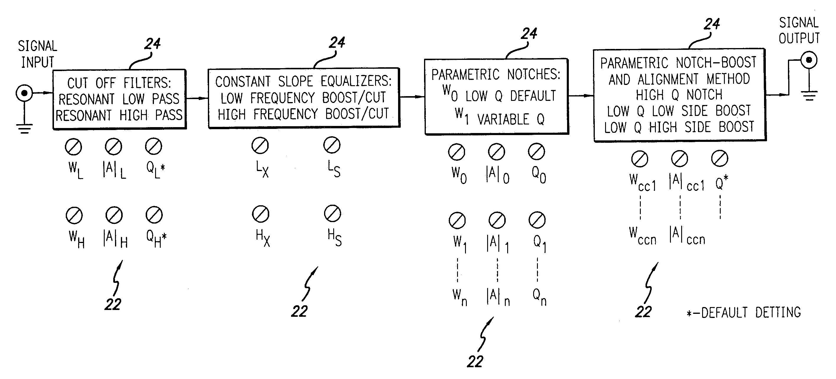
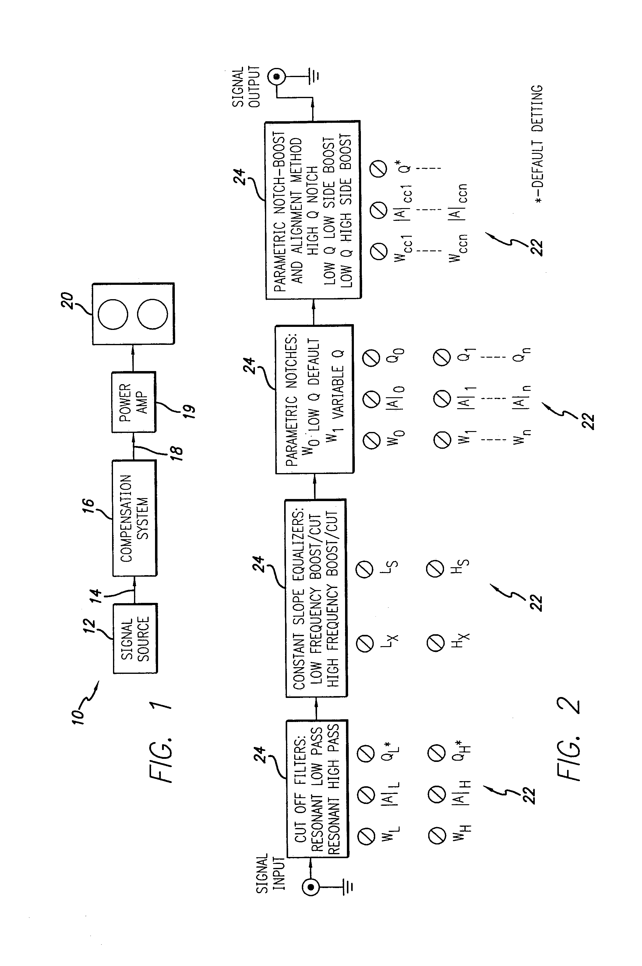
[0055]Referring now to the drawings, wherein like reference numerals denote like or corresponding parts throughout the drawing figures, and particularly to FIG. 1, there is shown a system 10 incorporating the present invention. The system 10 includes a signal source 12, for providing an electrical audio signal. The signal source may be, for example, a CD player. The output 14 from the signal source 12 is input to a compensation system 16 which employs detailed features and aspects of the present invention. The output 14 is processed by the compensation system 16 to produce a compensated electrical audio signal 18 which is fed to a power amplifier 19 and a loudspeaker 20.

[0056]With reference ...


PUM


Abstract

A sound compensation system alters an electrical audio signal for input to a sonic reproduction device having associated behavioral characteristics. The behavior characteristics of the device are defined by individual or groups of individual components of the sonic reproduction device and include mechanical, acoustic and electromagnetic behaviors. The model includes a plurality of filters that simulate at least one of the behavior characteristics of the sonic reproduction device. The filters are defined by digital signal processes or by analog circuits and are characterized by one or more of an associated frequency, time, phase and transient response. These responses combine to define an overall response for the model. The filters include adjustable parameters which are used to alter filter responses to produce responses that are conjugates to the responses of the unaltered filters and thus the sonic reproduction device. A controller modifies the parameters.

Description

RELATED APPLICATION[0001]This application claims the benefit of co-pending provisional application Ser. No. 60 / 148,412 filed Aug. 11, 1999.BACKGROUND OF THE INVENTION[0002]1. Field of the Invention[0003]This invention relates generally to a compensation method and system for use in sonic transmission and reproduction systems and more particularly to a compensation method and system that uses parametric values to control or adjust processes having transforms or models with properties or responses like the components or elements used in the transmission or reproduction system.[0004]2. Description of Related Art[0005]Most audio reproduction systems use electromechanical loudspeakers to acoustically reproduce audio signals. The electrical, mechanical, and acoustical properties of the loudspeakers are often less than ideal, causing distortions, response anomalies, and other coloration of the sound. Many techniques are used to compensate for the loudspeaker's characteristics in order to i...

Claims


Application Information

Patent Timeline
IPC IPC(8): H03G3/00H04R29/00
CPCH03G5/005
Inventor JOHNSON, KEITH O.LIMBERIS, ALEXMYRBERG, MATSONDERS, TIMOTHY E.
Owner MICROSOFT TECH LICENSING LLC
Learn More