Button structure for a timepiece and a timepiece having this button structure

a technology of button structure and timepiece, which is applied in the direction of electric winding, instruments, horology, etc., can solve the problems of difficulty in visual determination, reduced timepiece operability, and difficulty in second-stage input operation, so as to improve the design of the timepiece, reduce the number of buttons, and improve the button operability

Active Publication Date: 2008-02-26
SEIKO EPSON CORP
View PDF8 Cites 3 Cited by
  • Summary
  • Abstract
  • Description
  • Claims
  • Application Information

AI Technical Summary

Benefits of technology

[0012]The user can therefore easily visually recognize that there are first and second button members that can move relative to the base and the button structure enables two types of input.
[0027]A button structure for a timepiece and a timepiece having the button structure of this invention enables the user to easily visually recognize that the button mechanism enables two kinds of input, affords excellent operability, and enables locating a button enabling two types of input at one place on the timepiece.

Problems solved by technology

The first time a user operates this switch mechanism, for example, and sees the pushbutton exposed on the outside of the timepiece case member, it is difficult to visually determine whether the pushbutton has a single-stage operating mechanism or a two-stage operating mechanism, and timepiece operability is thus reduced.
The user may therefore find the operation of depressing the first button member and second button member together, that is, the second-stage input operation, difficult.

Method used


Image

  • Button structure for a timepiece and a timepiece having this button structure
  • Button structure for a timepiece and a timepiece having this button structure
  • Button structure for a timepiece and a timepiece having this button structure

Examples


Embodiment Construction

[0035]Preferred embodiments of the present invention are described below with reference to the accompanying figures wherein like parts are identified by the same reference numerals and further description of those parts is simplified or omitted.

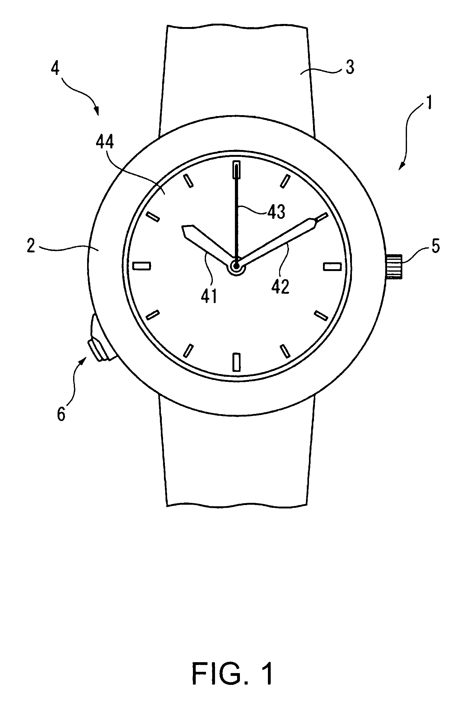
[0036]As shown in FIG. 1, a timepiece 1 according to this embodiment of the invention is an analog timepiece that has a case member 2, a band 3 that is attached to the case member 2, and a time display unit 4 assembled inside the case member 2.

[0037]The time display unit 4 has hour, minute, and second hands 41, 42, and 43, and a dial 44.

[0038]A crown 5 is disposed to the case member 2 at the three o'clock position, and a button 6 is disposed at the eight o'clock position.

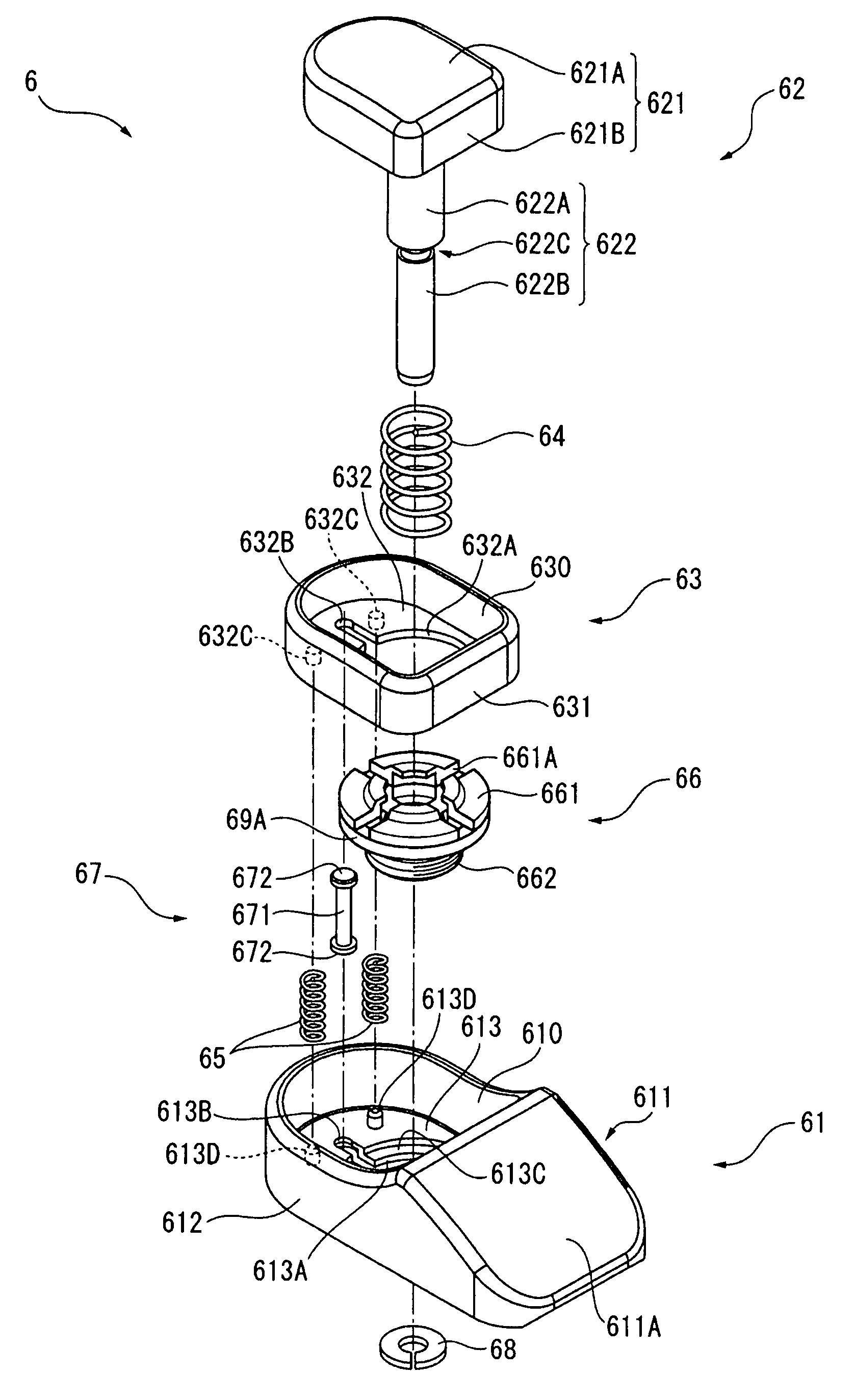
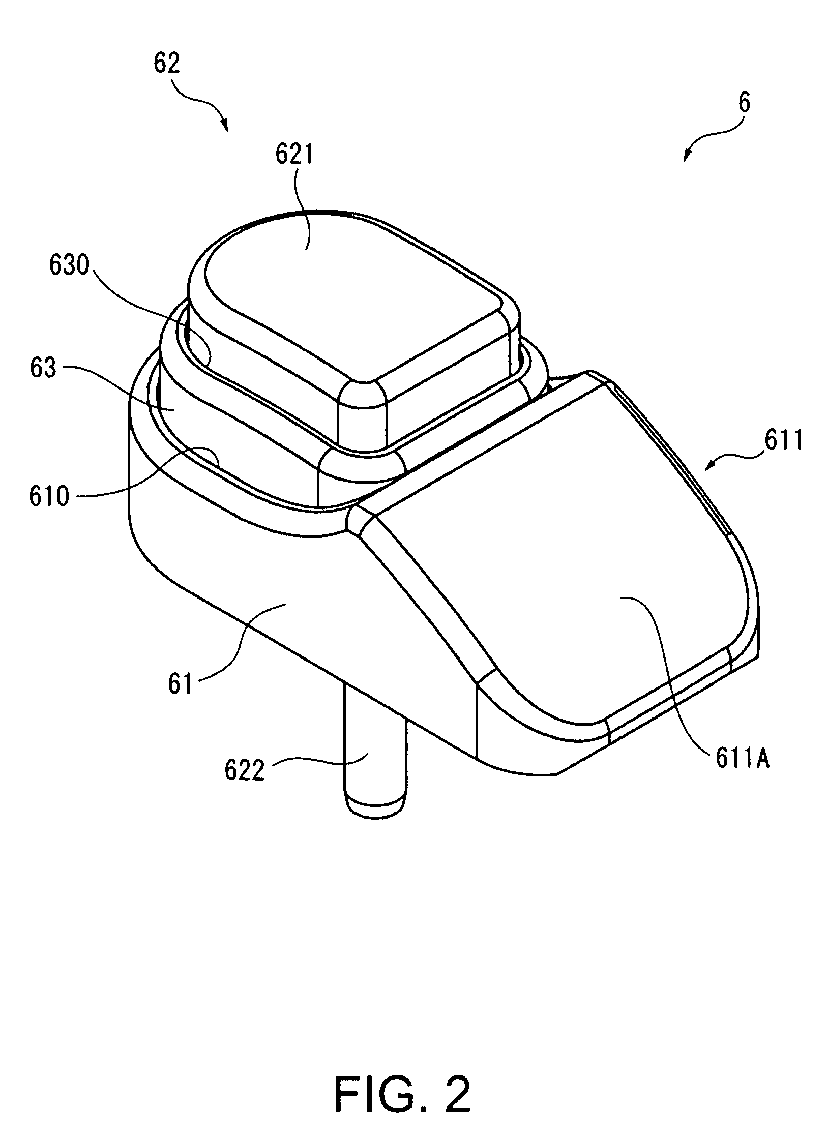
[0039]This button 6 is described in detail next with reference to FIG. 2 to FIG. 4.

[0040]As shown in FIG. 2 and FIG. 3 the button 6 has a button cover 61 as the base, a first button member 62, a second button member 63, a first coil spring 64 as a first urging member, a secon...


PUM


Abstract

A timepiece button structure has a base having a first cavity, a first button member, a second button member having a second cavity part, first and second urging members, and first and second movement-limiting members. The second button member is disposed to protrude from and recede into the first cavity part with the second urging member urging the second button member in the direction protruding from the first cavity part and the second movement-limiting member limiting movement in the protrusion direction. The first button member is disposed to protrude from and recede into the second cavity part with the first urging member urging the first button member in the direction protruding from the second cavity part and the first movement-limiting member limiting movement in the protrusion direction. The first button member moves alone in the receding direction until the first button member contacts the second button member when the first button member is pushed against the urging force of the first urging member in the direction receding into the second cavity part, and the first and second button members move together in the receding direction when the first button member is pushed further against the urging force of the first and second urging members in the direction receding into the first cavity part after the first button member contacts the second button member.

Description

BACKGROUND[0001]1. Technical Field[0002]The present invention relates to a button structure for a timepiece and to a timepiece having this button structure. More specifically, the invention relates to a button structure for a timepiece having a button member that is operated by being pushed into the case member of the timepiece, and to a timepiece having this button structure.[0003]2. Related Art[0004]The buttons on a timepiece are generally configured to implement one function by pressing the button, but switch mechanisms for implementing two functions using a single button are also available. See, for example, Japanese Unexamined Patent Appl. Pub. JP-A-2005-214795 (page 3 and FIG. 1).[0005]This type of timepiece switch mechanism uses a mechanism enabling a two-stage operation but from the outside appears the same as a button that has only a single stage operation, and the functionality of the button is therefore not readily apparent to the user. The first time a user operates this...

Claims


Application Information

Patent Timeline
Patent Type & Authority Patents(United States)
IPC IPC(8): H01H9/20H01H9/24H01H9/26G04G21/00
CPCG04B3/048G04C3/005H01H2221/078
Inventor OZAWA, NORIAKIKAWAHARA, KIMIKAZU
Owner SEIKO EPSON CORP
Why Eureka
Try Eureka