Relay

a technology of relays and light sources, applied in the field of relays, can solve the problems of narrow directional angles, difficult to view light, and less uniform light which exits from the display surface, and achieve the effect of easy visual recognition

Active Publication Date: 2016-11-01
ORMON CORP
View PDF13 Cites 0 Cited by
  • Summary
  • Abstract
  • Description
  • Claims
  • Application Information

AI Technical Summary

Benefits of technology

[0014]One or more embodiments of the present invention provides a relay which allows an operator to easily visually recognize even from an oblique direction that a light source (operation indicating light) is emitting light. One or more embodiments of the present invention optimizes the length of a light guide path which guides the light of the light source.

Problems solved by technology

However, according to the relay disclosed in Patent Literature 1, the light which exits from the display surface is less uniform, and has a narrow directional angle.
Therefore, even in a case where light exits from the display surface due to emission of the light from the light source, it is difficult to view the light when the relay is observed from an oblique direction (a direction oblique with respect to a direction perpendicular to the upper surface of the relay).
This is very troublesome.
This diffuse reflection surface does not allow an operator to clearly check, from the oblique direction, a state where the light source emits light.
However, this lens is not a lens for diffusing light but a lens for collecting light.
Therefore, even according to the relay disclosed in Patent Literature 2, it is remarkably difficult to find, from an oblique direction, that the light source emits light, though it is possible to easily find that from a direction perpendicular to an upper surface of a case.

Method used


Image

  • Relay
  • Relay
  • Relay

Examples


embodiment 1

Modification of Embodiment 1

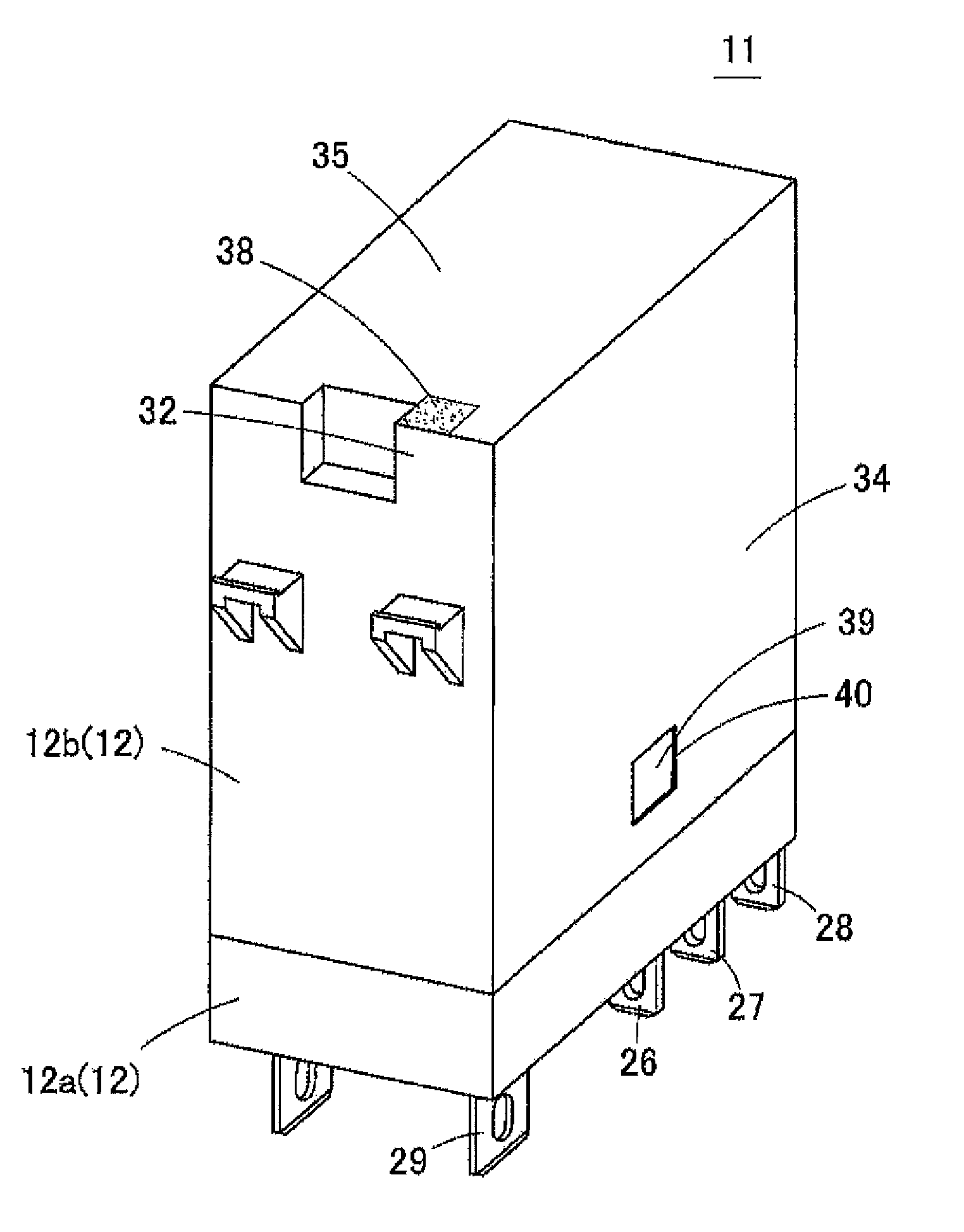
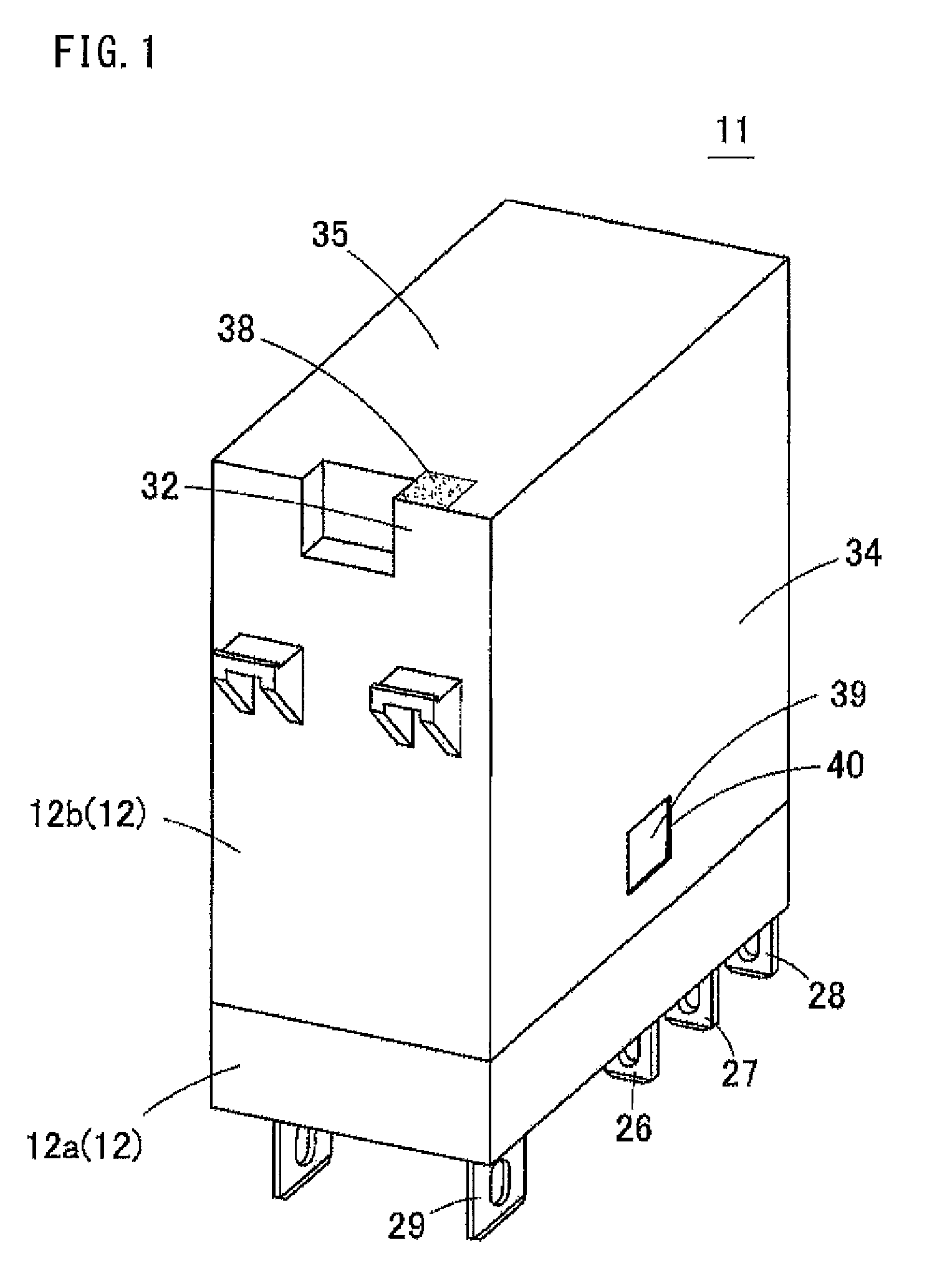
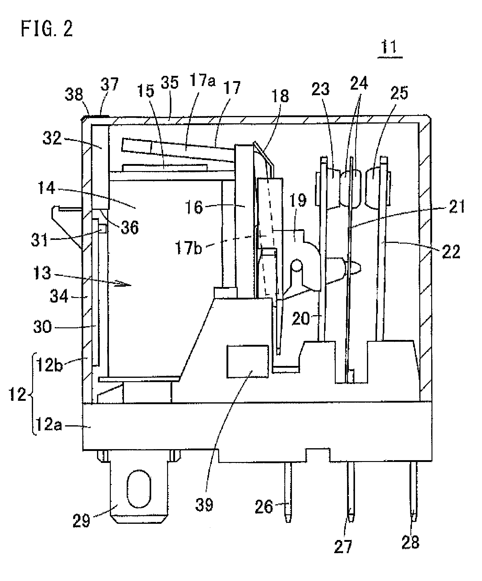
[0060]A modification of Embodiment 1 of the present invention will be described below. Embodiment 1 has described a case where the diffusion structure 38 is the rough surface obtained by randomly forming the minute convexoconcave shape on the light exit surface 37. The diffusion structure 38 may be a diffusion sheet bonded to the light exit surface 37 (not illustrated). Alternatively, the diffusion structure 38 may be light-diffusing particles dispersed in the vicinity of the light exit surface 37 in the light guide path 32 (not illustrated).

Embodiment 2

[0061]FIG. 8 is a perspective view of a relay 51 of Embodiment 2 of the present invention. FIG. 9 is a perspective view illustrating a structure of a portion which is cut from the relay 51 which structure is in the vicinity of a light guide path. FIG. 10(A) is a view obtained when the perspective view of FIG. 9 is viewed from a side surface. FIG. 10(B) is a cross-sectional view taken along X-X line of FIG....

embodiment 2

Modification of Embodiment 2

[0068]Where a thickness reduction part 52 is provided is not limited to an outer side surface of a light guide path 32. The thickness reduction part 52 may be provided in, for example, an inner side surface of the light guide path 32 (see FIG. 13). Alternatively, the thickness reduction part 52 may be provided in a right and / or left side surface of the light guide path 32 (a side surface of the light guide path 32 which side surface is perpendicular to an outer surface of a side wall 34) (not illustrated).

Other Embodiments

[0069]FIGS. 14(A)-14(B) are a perspective view and a side view, respectively, which illustrate a structure of a light guide path 32 of a relay of another embodiment of the present invention. The light guide path 32 may be independent from a side wall 34 of a housing 12b and a top board 35, and may be isolated from the housing 12b (see FIGS. 14(A)-14(B)). In this case, a diffusion structure 38 may be provided on a light exit surface 37, o...


PUM


Abstract

A relay has a case, a relay body disposed in the case, a light source disposed in the case that emits light in accordance with an operation of the relay body, a light guide path which that receives, via a first end surface, the light emitted from the light source, and causes the light to exit outward from a second end surface, and a diffusion structure disposed in an optical path of the light which exits from the second end surface of the light guide path.

Description

CROSS-REFERENCE TO RELATED APPLICATIONS[0001]This Nonprovisional application claims priority under 35 U.S.C. §119(a) on Patent Application No. 2014-030041 filed in Japan on Feb. 19, 2014, the entire contents of which are hereby incorporated by reference.BACKGROUND[0002]1. Technical Field[0003]The present invention relates to a relay. Specifically, the present invention relates to a relay having a function of emitting light to indicate an operation.[0004]2. Related Art[0005]Some conventional relays include an operation indicating light so that an operator easily checks an operation of the relay. The operation indicating light is turned on or off in accordance with an opening or closing operation of the relay. Generally, in order for an operator to easily visually recognize, from an outside of the relay, whether the operation indicating light is in an ON or OFF state, the relay is desirably configured so that the operator can view light of the operation indicating light from a surface...

Claims


Application Information

Patent Timeline
Patent Type & Authority Patents(United States)
IPC IPC(8): F21V7/04F21V8/00F21V11/00G02B5/02
CPCG02B6/0008G02B5/0226H01H9/161H01H50/08
Inventor HIROSE, YUJISHINOHARA, MASAYUKITANOUE, YASUHIROMIYAMOTO, HIROYUKIOSUMI, YOSHIMASAHIROTA, KAZUHIDE
Owner ORMON CORP
Why Eureka
Try Eureka