Display control apparatus and imaging apparatus

a control apparatus and display technology, applied in the field of display control apparatus and imaging apparatus, can solve the problems of difficult to confirm presence or absence of false colors, and achieve the effect of easy visual recognition, easy visual recognition, and easy confirmation of presen

Active Publication Date: 2020-02-20
SONY CORP
View PDF11 Cites 1 Cited by
  • Summary
  • Abstract
  • Description
  • Claims
  • Application Information

AI Technical Summary

Benefits of technology

The patent is about a display control apparatus and an imaging apparatus that can easily show the user the position where image quality is declining, either because of resolution or false color. This is achieved by enhancing the region where resolution changes or false color is generated in response to changing lowpass characteristics. This makes it easy for the user to confirm the presence or absence of false color in a taken image, even on a small screen. The technical effect of this patent is to improve the user experience and make the image quality decline easier to visually recognize.

Problems solved by technology

However, a screen of the viewfinder is not so large, which causes an issue that it is not easy to confirm presence or absence of false color generated in the taken image.

Method used


Image

  • Display control apparatus and imaging apparatus
  • Display control apparatus and imaging apparatus
  • Display control apparatus and imaging apparatus

Examples


embodiment

1. Embodiment

[Configuration]

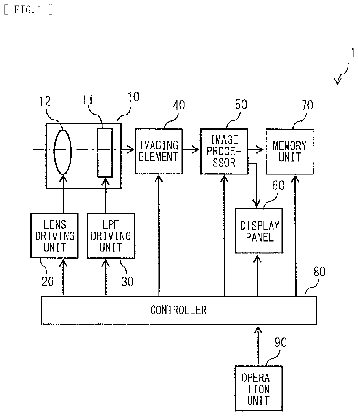
[0046]FIG. 1 illustrates an example of a schematic configuration of an imaging apparatus according to an embodiment of the present disclosure. The imaging apparatus 1 includes, for example, an imaging optical system 10, a lens driving unit 20, an LPF driving unit 30, an imaging element 40, and an image processor 50. The imaging apparatus 1 further includes, for example, a display panel 60, a memory unit 70, a controller 80, and an operation unit 90.

(Imaging Optical System 10)

[0047]The imaging optical system 10 includes, for example, a variable optical LPF (Low Pass Filter) 11 and a lens 12. The lens 12 forms an optical subject image on the imaging element 40. The lens 12 includes a plurality of lenses, and is driven by the lens driving unit 20, thereby allowing at least one lens to be moved. Thus, the lens 12 allows for optical focus adjustment and zoom adjustment. The variable optical LPF 11 removes a high spatial frequency component included in light, a...

modification examples

2. Modification Examples

[0151]Next, description is given of modification examples of the imaging apparatus 1 according to the foregoing embodiment.

modification example a

[0152]In the foregoing embodiment, the image processor 50 makes the effect of the variable optical LPF 11 maximum or substantially maximum in the step S102. However, the image processor 50 may set the effect of the variable optical LPF 11 to any value in the step S102. In this case, the image processor 50 may derive the saturation data 33 after performing processing of eliminating false color in a region where there is a possibility that false color is generated of the obtained image data In such a case, it is possible to reduce time necessary to obtain an appropriate set value for the variable optical LPF 11 as compared with a case where the effect of the variable optical LPF 11 is maximum or substantially maximum at first.


PUM


Abstract

A display control apparatus according to an embodiment of the present disclosure includes a display controller that performs enhancement on a region where resolution is changed in response to changing of lowpass characteristics or a region where false color is generated or changed in response to changing of the lowpass characteristics in image data generated on the basis of light incident via a lowpass filter.

Description

TECHNICAL FIELD[0001]The present disclosure relates to a display control apparatus and an imaging apparatus.BACKGROUND ART[0002]In a case where a typical single-plate digital camera uses a Bayer coding imager, it is necessary to restore lost information through performing demosaicing processing on image data obtained by the imager. However, it is difficult to fully derive the lost information in principle, which unavoidably causes a decline in resolution and occurrence of artifacts.[0003]It is therefore considered to provide a lowpass filter between a lens and the imager. In such a case, adjusting an effect of the lowpass filter makes it possible to reduce false color that is one of the artifacts. It is to be noted that, for example, an optical lowpass filter disclosed in the following PTL 1 is usable as a lowpass filter that reduces moire.CITATION LISTPatent Literature[0004]PTL 1: Japanese Unexamined Patent Application Publication No. 2006-08045SUMMARY OF THE INVENTION[0005]Inciden...

Claims


Application Information

Patent Timeline
Patent Type & Authority Applications(United States)
IPC IPC(8): H04N5/232G03B11/00H04N23/12
CPCH04N5/23293G03B11/00G03B17/18H04N23/00H04N23/60H04N25/11H04N23/12H04N23/63
Inventor NOGUCHI, SHOHEI
Owner SONY CORP
Why Eureka
Try Eureka