Heat exchanger with leakage vent

a technology of leakage vent and heat exchanger, which is applied in the direction of heat exchanger sealing arrangement, light and heating apparatus, laminated elements, etc., can solve the problems of only being used reluctantly, heat exchangers may break, and the connection may break inside the heat exchanger

Inactive Publication Date: 2008-03-04
DANFOSS AS
View PDF17 Cites 30 Cited by
  • Summary
  • Abstract
  • Description
  • Claims
  • Application Information

AI Technical Summary

Benefits of technology

[0008]According to the invention, a separation zone is created around the connections, so as to block off the medium that is not to reach the connection in

Problems solved by technology

One problem existing in such heat exchangers is that a brazing at a connection may break inside the heat exchanger.
This has meant that such heat exchangers have been used only reluctantly e.g. for the cooling of machinery where the oil lubricating the machine is cooled by heat exchange with water.
Water mixing into the oil could cause catastrophic results for the machine, which could in the worst case

Method used


Image

  • Heat exchanger with leakage vent
  • Heat exchanger with leakage vent
  • Heat exchanger with leakage vent

Examples


Embodiment Construction

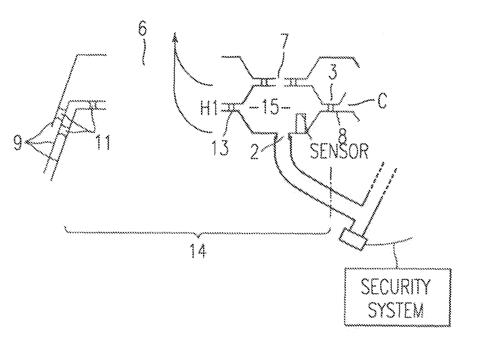
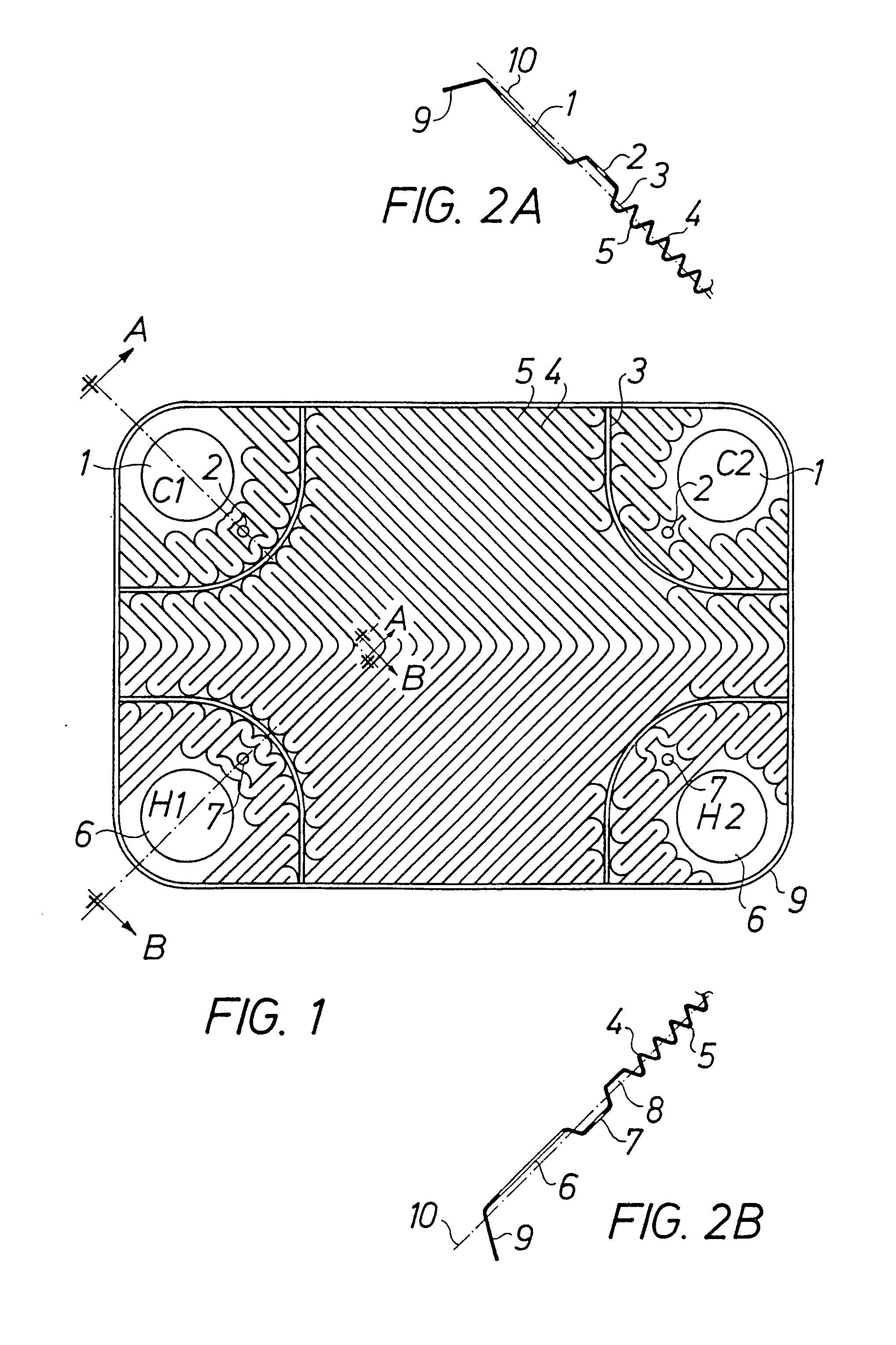
[0016]FIG. 1 shows a plate for a heat exchanger according to the present invention. As is conventional, the plate has a groove pattern and connections. The grooves have peaks 4 and valleys 5. A cold medium has an inlet at C2 and an outlet at C1. A hot medium has an inlet at H2 and an outlet at H1. It is to be understood that the groove pattern may be varied in many different ways without deviating from the scope of the invention.

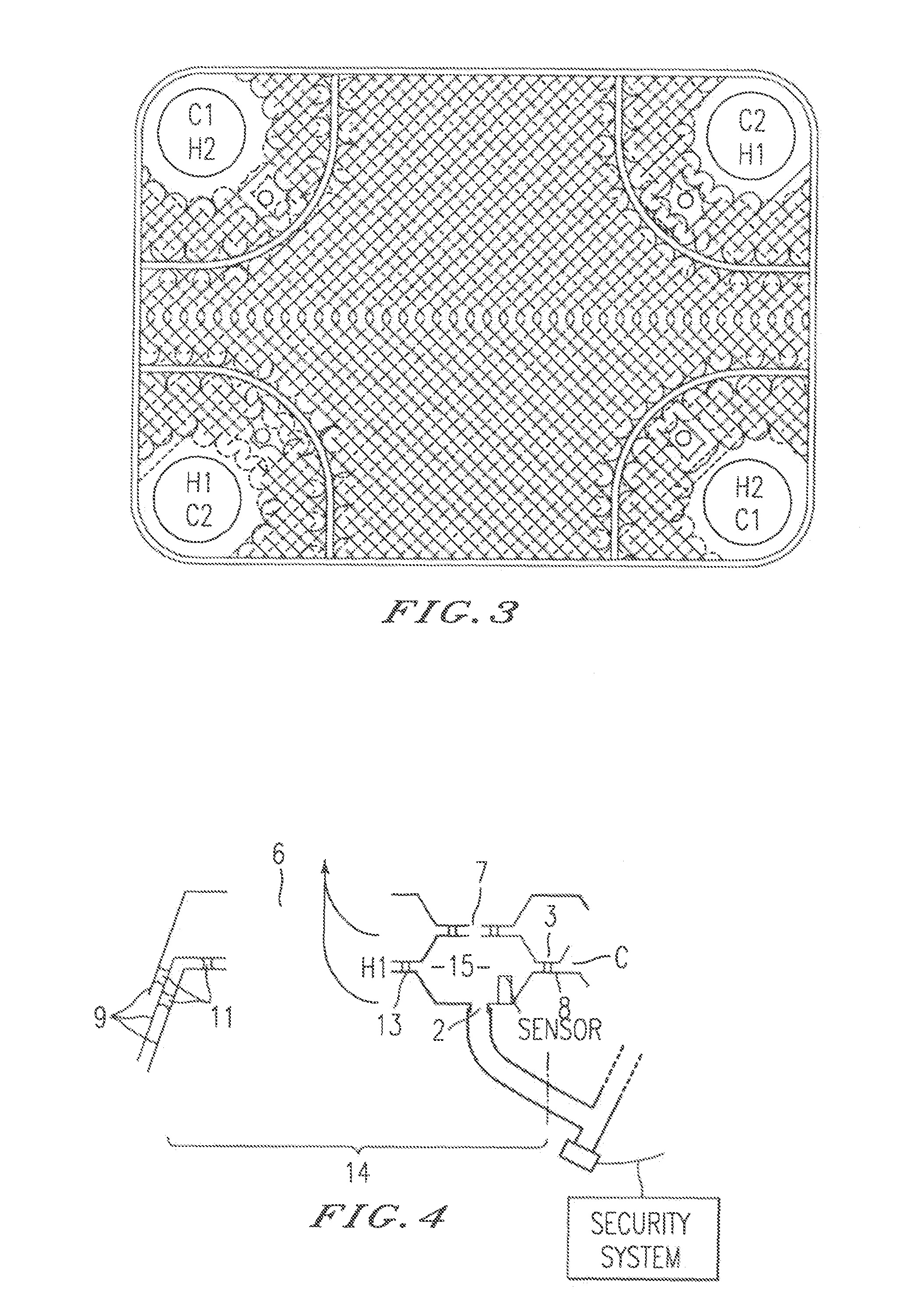
[0017]A heat exchanger is created by assembling a number of identical plates into a pack. Every other plate is turned 180° so as to create a crossing pattern and to form channels for the media between alternating pairs of plates, as is well known to those skilled in the art. FIG. 3 shows a lower plate visible through an upper plate in order to illustrate the crossing pattern. On one side of the pack there is also a bottom plate (not shown) for closing the connections on one side. The whole pack is brazed together in an oven so as to create brazing points whe...


PUM


Abstract

A heat exchanger with a leakage vent. A fully brazed heat exchanger has an arrangement preventing the two media inside the heat exchanger from mixing in case of leakage. The heat exchanger includes plates having a pattern of grooves and inlet and outlet connections. The plates are placed in a pack and brazed together so as to form separate channels for two media between alternating pairs of plates. A separation zone is created around the connection so as so block off the medium that is not to reach the respective connection. The other medium can flow on by. A leakage vent to the exterior is provided in the separation zone so as to allow detection of any leakage.

Description

BACKGROUND OF THE INVENTION[0001]1. Field of the Invention[0002]The present invention relates to a heat exchanger with a leakage vent, and more particularly to a fully brazed heat exchanger having an arrangement preventing the two media inside the heat exchanger from mixing in case of leakage. The invention also allows quick detection of the leakage. A separation zone is provided at each connection to the heat exchanger. The separation zone comprises a blocked-off space with leakage vents, where any leakage can be detected.[0003]2. Discussion of the Background[0004]The fully brazed heat exchangers of today comprise of brazed packs of plates lacking any possibility of internal inspection. One problem existing in such heat exchangers is that a brazing at a connection may break inside the heat exchanger. An invisible leak is then created inside the heat exchanger, whereupon the media become mixed without this being detectable from outside the heat exchanger. This has meant that such he...

Claims


Application Information

Patent Timeline
IPC IPC(8): F28F3/00F28F11/00F28D9/00
CPCF28D9/005F28F3/005F28F2265/16
Inventor PERSSON, LARS
Owner DANFOSS AS
Why Eureka
Try Eureka