Connector

a technology of connecting rods and connectors, applied in the direction of coupling device connection, securing/insulating coupling contact members, electrical devices, etc., can solve the problem of additional space, and achieve the effect of increasing the space for preventing the withdrawal of metal terminals

Inactive Publication Date: 2008-03-18
YAZAKI CORP
View PDF6 Cites 2 Cited by
  • Summary
  • Abstract
  • Description
  • Claims
  • Application Information

AI Technical Summary

Benefits of technology

[0009]This invention has been made in view of the above circumstances, and an object of the invention is to provide a connector in which means for preventing withdrawal of a front holder is provided at a lance so as to contribute to a compact design of the connector, and also a retaining force for preventing withdrawal of a metal terminal can be increased.
[0015]the front holder has a lance holding portion which enters the elastic deformation space to prevent elastic deformation of the lance when the front holder is mounted into the front holder insertion space of the connector housing from the front side thereof; and
[0016]an engagement portion is provided between the lance and the lance holding portion, and when the lance and the lance holding portion are engaged with each other, the engagement portion prevents forward movement of the front holder, and also transmits a rearward force, applied from the metal terminal to the lance, to the front holder.
[0018]In the connector of the construction of the above Paragraph (1), the withdrawal of the front holder can be prevented directly by the lance. Therefore, retaining means for preventing the withdrawal of the front holder does not need to be provided at other portion of the housing than the lance, and this contributes to a compact design of the connector. And besides, in the connector of the construction of the above Paragraph (1), the front holder assists the lance in retaining the metal terminal against withdrawal, and therefore a force for retaining the metal terminal can be increased. Furthermore, in the connector of the construction of the above Paragraph (1), when the metal terminal is in a half-inserted condition, the lance is kept elastically deformed to be received in the elastic deformation space, and therefore the front holder can not be inserted into the predetermined position. Therefore, the half-inserted condition of the metal terminal can be detected from this. In this case, the lance has the engagement portion for engagement with the front holder, and therefore a surface of the lance for abutting against the front holder can be made large, and therefore an abutting or striking force can be set to a large value, and the performance of detection of such a half-inserted condition of the metal terminal can be enhanced.
[0019]In the connector of the construction of the above Paragraph (2) the front holder, when attached to the connector housing, presses and displaces the lance in such a direction as to more firmly engage the lance with the metal terminal, and therefore the force for retaining the metal terminal can be further increased, Furthermore, a clearance between the metal terminal and the lance can be reduced, and therefore the shaking or movement of the metal terminal can be reduced.
[0020]In the present invention, there can be provided the connector in which the compact design of the connector can be achieved, and besides the retaining force for preventing the withdrawal of the metal terminal is further increased.

Problems solved by technology

In the above conventional connector, the retaining means for preventing the withdrawal of the front holder is provided at the place spaced apart from the lances, and therefore an additional space is required, and this has sometimes been an obstacle to a compact design of the connector.

Method used


Image

  • Connector
  • Connector
  • Connector

Examples


Embodiment Construction

[0026]A preferred embodiment of the present invention will now be described with reference to the drawings.

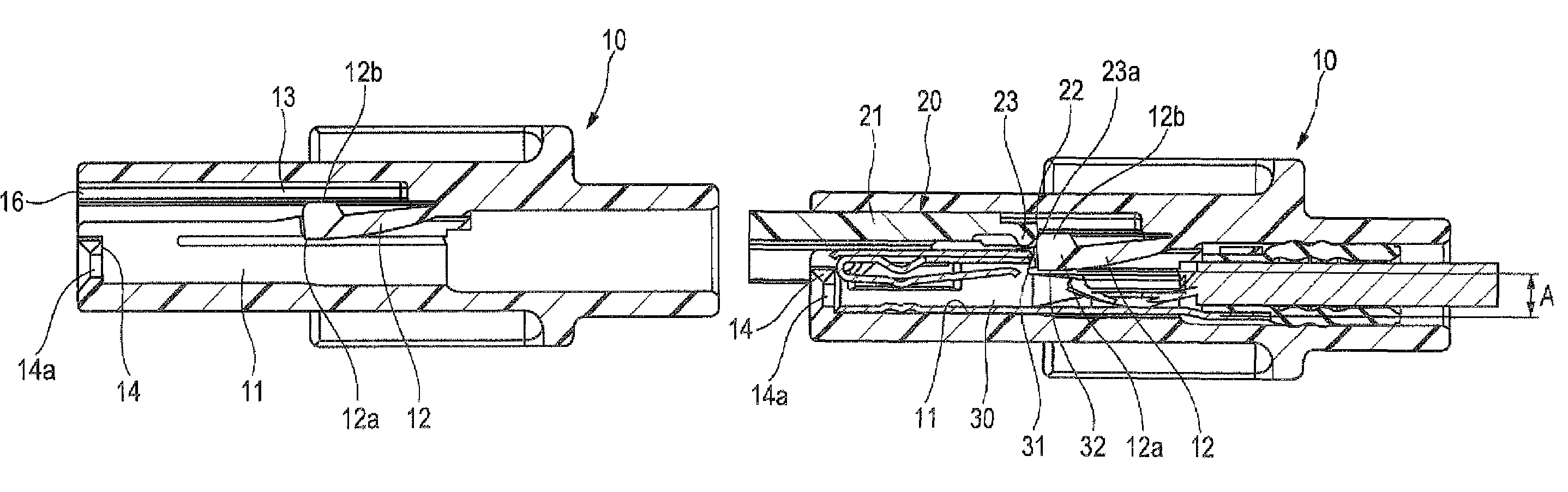
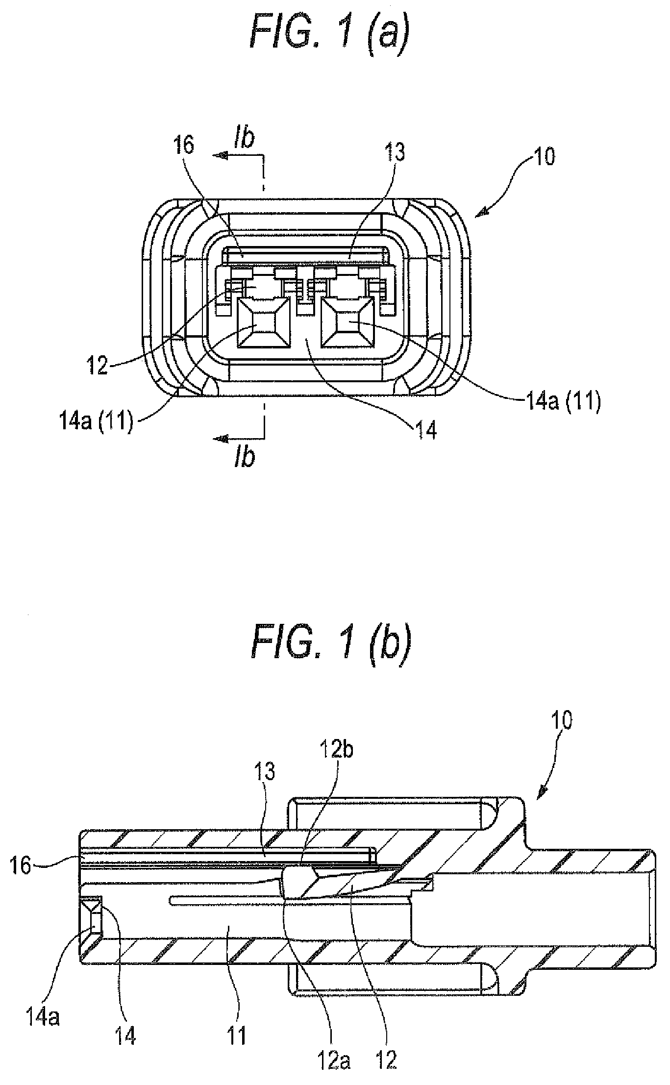
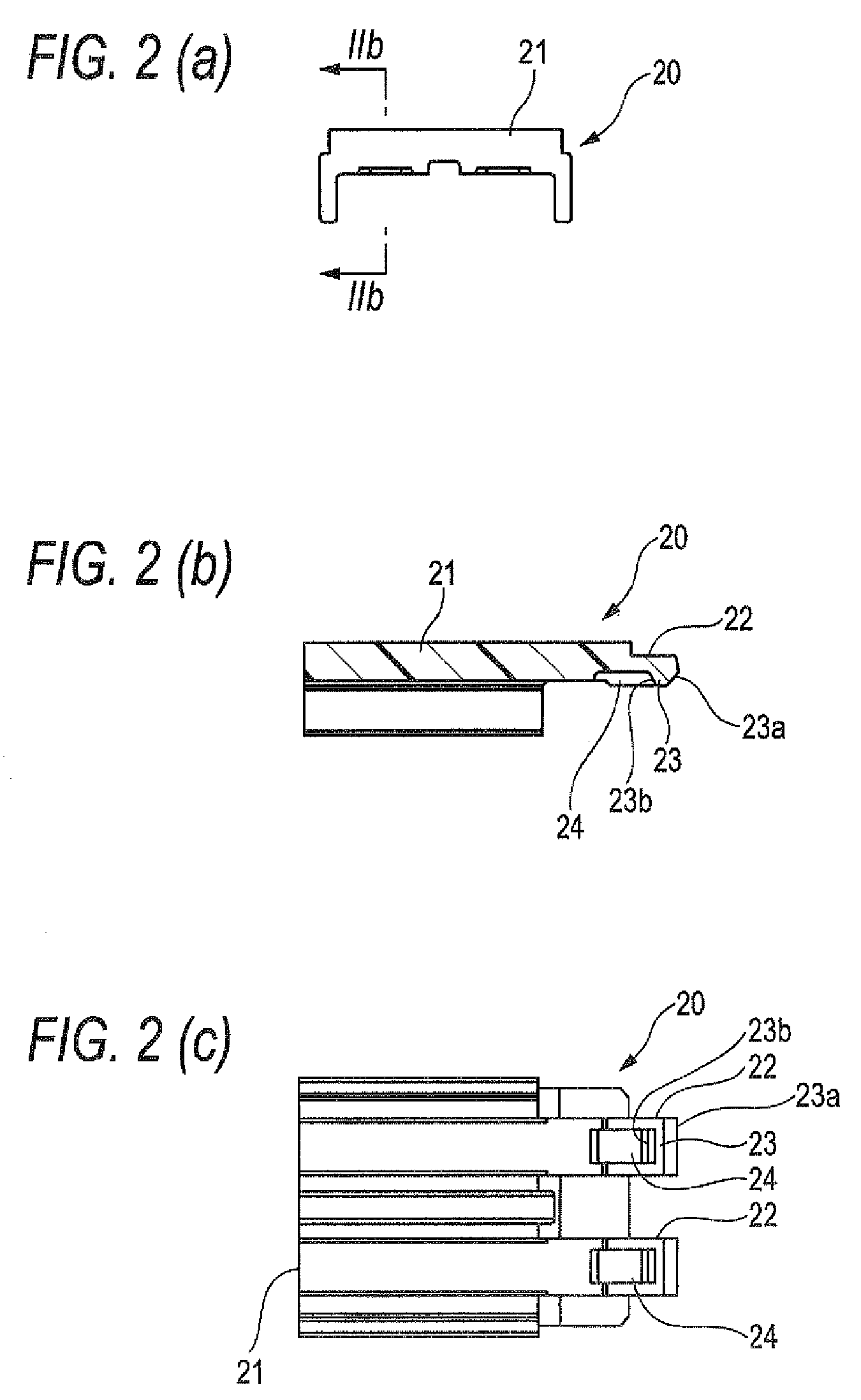
[0027]FIGS. 1A and 1B show the construction of a connector housing of a connector embodying the invention, and FIG. 1A is a front-elevational view, and FIG. 1B is a cross-sectional view taken along the line Ib-Ib of FIG. 1A. FIGS. 2A, 2B and 2C show the construction of a front holder of the connector of the invention, and FIG. 2A is a front-elevational view, and FIG. 2B is a cross-sectional view taken along the line IIb-IIb of FIG. 2A, and FIG. 2C is a bottom view. FIGS. 3A and 3B show a condition in which the front holder of FIGS. 2A to 2C is half inserted in the connector housing of FIGS. 1A and 1B from a front side thereof after metal terminals are inserted into the connector housing, and FIG. 3A is a front-elevational view, and FIG. 3B is a cross-sectional view taken along the line IIIb-IIIb of FIG. 3A. FIGS. 4A and 4B show a condition in which the front holder is completel...


PUM


Abstract

To provide a connector in which a compact design of the connector can be achieved, and besides a retaining force for preventing withdrawal of a metal terminal can be further increased, a connector housing 10 includes terminal receiving chambers 11 into which metal terminals 30 can be inserted, respectively, from a rear side, elastic lances 12 for respectively retaining the metal terminals 30 to prevent rearward withdrawal of the metal terminals 30, an elastic deformation space 13 for the lances, and a front holder insertion space 16 which is provided at a front side of the elastic deformation space in continuous relation thereto such that a front holder can be inserted into a predetermined position in the front holder insertion space from the front side. The front holder 20 has lance holding portions 22 which enter the elastic deformation space to prevent elastic deformation of the lances when the front holder is mounted into the connector housing from the front side, and the lance and the lance holding portion have an engagement convex portion 12b and a retaining portion 23, respectively, which can be engaged with each other to prevent forward movement of the front holder and also to transmit a rearward force, applied from the metal terminal to the lance, to the front holder.

Description

BACKGROUND OF THE INVENTION[0001]1. Field of the Invention[0002]This invention relates to a connector in which elastic deformation of a lance is prevented by the use of a front holder, thereby increasing a retaining force for preventing withdrawal of a metal terminal.[0003]2. Description of the Related Art[0004]Patent Literature 1 and Patent Literature 2 disclose conventional connectors in which elastic deformation of lances are prevented by the use of a front holder. In this kind of connector, metal terminals are inserted into respective terminal receiving chambers in a connector housing from a rear side thereof, and in this condition the front holder is attached to the connector housing from the front side thereof, so that lance holding portions of the front holder are inserted into an elastic deformation space for the lances, thereby preventing elastic deformation of the lances, thus retaining the metal terminals in a double manner.[0005]In this case, generally, retaining means f...

Claims


Application Information

Patent Timeline
Patent Type & Authority Patents(United States)
IPC IPC(8): H01R13/514
CPCH01R13/4223H01R13/4365
Inventor SUGIYAMA, OSAMUIWAHORI, YOSHIHIROAKIYAMA, MITSUO
Owner YAZAKI CORP
Why Eureka
Try Eureka