System and method for removing heat from a subscriber optical interface

a subscriber optical interface and subscriber technology, applied in the direction of electrical apparatus casings/cabinets/drawers, lighting and heating apparatus, coupling device connections, etc., can solve the problems of enclosures being exposed to direct sunlight, difficult to mount inside structures, and inability to use in front of this type of equipment, so as to minimize the transfer of heat from the surrounding environment into the enclosure via the fins and maximize the effect of heat transfer

Inactive Publication Date: 2008-04-08
ARRIS SOLUTIONS
View PDF197 Cites 38 Cited by
  • Summary
  • Abstract
  • Description
  • Claims
  • Application Information

AI Technical Summary

Benefits of technology

[0009]The present invention is generally drawn to a system and method for removing heat from an enclosure or housing of a subscriber optical interface. The subscriber optical interface can support optical communications between a subscriber and a data service hub. The system and method of the present invention can comprise selecting a position of fins that are part of a finned array designed to remove heat from a housing or enclosure of a subscriber optical interface. The position of the fins relative to entire subscriber optical interface can be chosen such that transfer of heat from the surrounding environment into the enclosure via the fins is minimized and the transfer of heat from the fins to the environment is maximized.
[0011]When a subscriber optical interface housing is attached to a structure such that a partially enclosed volume of space remains between the structure and the subscriber optical interface housing, this partially enclosed volume of space can produce a chimney effect when heat from the subscriber optical interface housing is intended to flow from the fins into the air. This chimney effect can refer to a fluid such as air within the partially enclosed space that is heated by the fins and that rises upward when the ambient or surrounding fluid is cooler relative to the heated fluid.
[0012]The shape or position (or both) of the fins can be selected to the maximize the chimney effect mentioned above. This means that the shape of the fins can be selected to maximize heat transfer from the fins to the ambient air that is present in the enclosed volume of space between the subscriber optical interface and the structure in which the subscriber optical interface is attached. Specifically, the shape that includes a size of the fins can be selected to maximize the chimney effect. According to one exemplary embodiment, the fins can comprise a triangular cross-sectional shape.
[0014]In addition to shaping, sizing, positioning, and coloring the fins to maximize the chimney effect, the present invention can comprise selecting a position of heat producing elements such that this chimney effect is maximized. This means that first heat producing elements that produce more heat than second heat producing elements can be positioned below the second heat producing elements.
[0024]According to another exemplary embodiment, the subscriber optical interface can be shaped to form an internal chimney structure that is entirely surrounded by a housing of the subscriber optical interface. In other words, the subscriber optical interface housing can comprise a hollow cavity that is formed by internal walls of the subscriber optical interface. Within this chimney structure, a plurality of fins can be positioned within the chimney structure to transfer heat. The fins within the chimney structure can be shaped and positioned to maximize the chimney effect of the chimney structure. According to one exemplary embodiment, the subscriber optical interface housing can comprise a parallel piped shaped structure.

Problems solved by technology

In other words, usually the number of cables connected to an enclosure of a NID makes it difficult to mount it inside a structure and to have the NID be aesthetically pleasing to the subscriber.
In some types of equipment, heat fins are used for this purpose, but they are unattractive and thus cannot be used in front of this type of equipment.
Also, in some cases, the enclosure could be exposed to direct sunlight.
When this happens, heat sinks on the front of the unit can be more harmful than good since the fins may become heated by the sunlight and cause the heat fins to work in reverse by injecting heat into the enclosure instead of removing it.
These numerous heat producing components tend to exacerbate the problems with this smaller enclosure approach.

Method used


Image

  • System and method for removing heat from a subscriber optical interface
  • System and method for removing heat from a subscriber optical interface
  • System and method for removing heat from a subscriber optical interface

Examples


Embodiment Construction

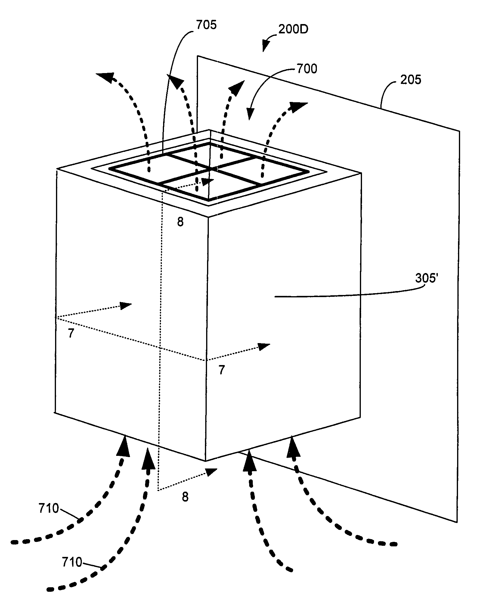
[0043]The present invention is generally drawn to a system and method for removing heat from an enclosure or housing of a subscriber optical interface. When a subscriber optical interface housing is attached to a structure such that a partially enclosed volume of space remains between the structure and the subscriber optical interface housing, this partially enclosed volume of space can produce a chimney effect when heat from the subscriber optical interface housing is intended to flow from the fins towards the structure. This chimney effect can refer to a fluid such as air within the partially enclosed space that is heated by the fins and that rises upward when the ambient or surrounding fluid is cooler relative to the heated fluid. The shape or position (or both) of the fins can be selected to the maximize chimney effect mentioned above.

[0044]According to another exemplary embodiment, the subscriber optical interface can be shaped to form an internal chimney structure that is enti...


PUM


Abstract

A system and method removes heat from an enclosure or housing of a subscriber optical interface. When a subscriber optical interface housing is attached to a structure such that a partially enclosed volume of space remains between the structure and the subscriber optical interface housing, this partially enclosed volume of space can produce a chimney effect when heat from the subscriber optical interface housing is intended to flow from fins towards the structure. This chimney effect can refer to a fluid such as air within the partially enclosed space that is heated by the fins and that rises upward when the ambient or surrounding fluid is cooler relative to the heated fluid. According to another exemplary embodiment, the subscriber optical interface can be shaped to form an internal chimney structure that is entirely surrounded by a housing of the subscriber optical interface.

Description

STATEMENT REGARDING RELATED APPLICATIONS[0001]This application is a divisional of and claims priority to application Ser. No. 10 / 337,620 filed Jan. 7, 2003 now U.S. Pat. No. 7,038,910, entitled “System and Method for Removing Heat from a Subscriber Optical Interface,” the entire contents of which are hereby incorporated by reference. U.S. patent application Ser. No. 10 / 337,620 claims priority to the provisional patent application entitled, “Apparatus for Dissipating Heat Generated by Equipment Mounted to a Wall,” filed on Jan. 7, 2002 and assigned U.S. Application Ser. No. 60 / 344,805. The entire contents of the provisional patent application mentioned above is hereby incorporated by reference.[0002]The present application is also related to U.S. non-provisional patent application entitled, “System and Method for Communicating Optical Signals between a Data Service Provider and Subscribers”, filed on Jul. 5, 2001 and assigned U.S. application Ser. No. 09 / 899,410. The entire contents ...

Claims


Application Information

Patent Timeline
Patent Type & Authority Patents(United States)
IPC IPC(8): H05K7/20
CPCH05K7/20127H05K7/20445
Inventor HODGE, RONALD L.FARMER, JAMES O.
Owner ARRIS SOLUTIONS
Why Eureka
Try Eureka