Dip stick

Active Publication Date: 2008-04-22
GROUP ONE
View PDF14 Cites 16 Cited by
  • Summary
  • Abstract
  • Description
  • Claims
  • Application Information

AI Technical Summary

Benefits of technology

[0008]The inventive dip stick assembly provides an automatic technique for cleaning the dip stick assembly. The dip stick is placed in communication with an oil reservoir. The wipers are biased into engagement with the dip stick. The wiper, however, is prevented from engaging the dip stick by the block. The block is then removed to allow the wiper to contact the

Problems solved by technology

Specifically, the technique is messy.
Also, the cloth or such used to wipe the dip stick must be thrown away because it is difficult or impractical to clean, both wasting the cloth and causing the inconvenience of its disposal.
Oil is also wasted because oil

Method used


Image

  • Dip stick
  • Dip stick
  • Dip stick

Examples


Embodiment Construction

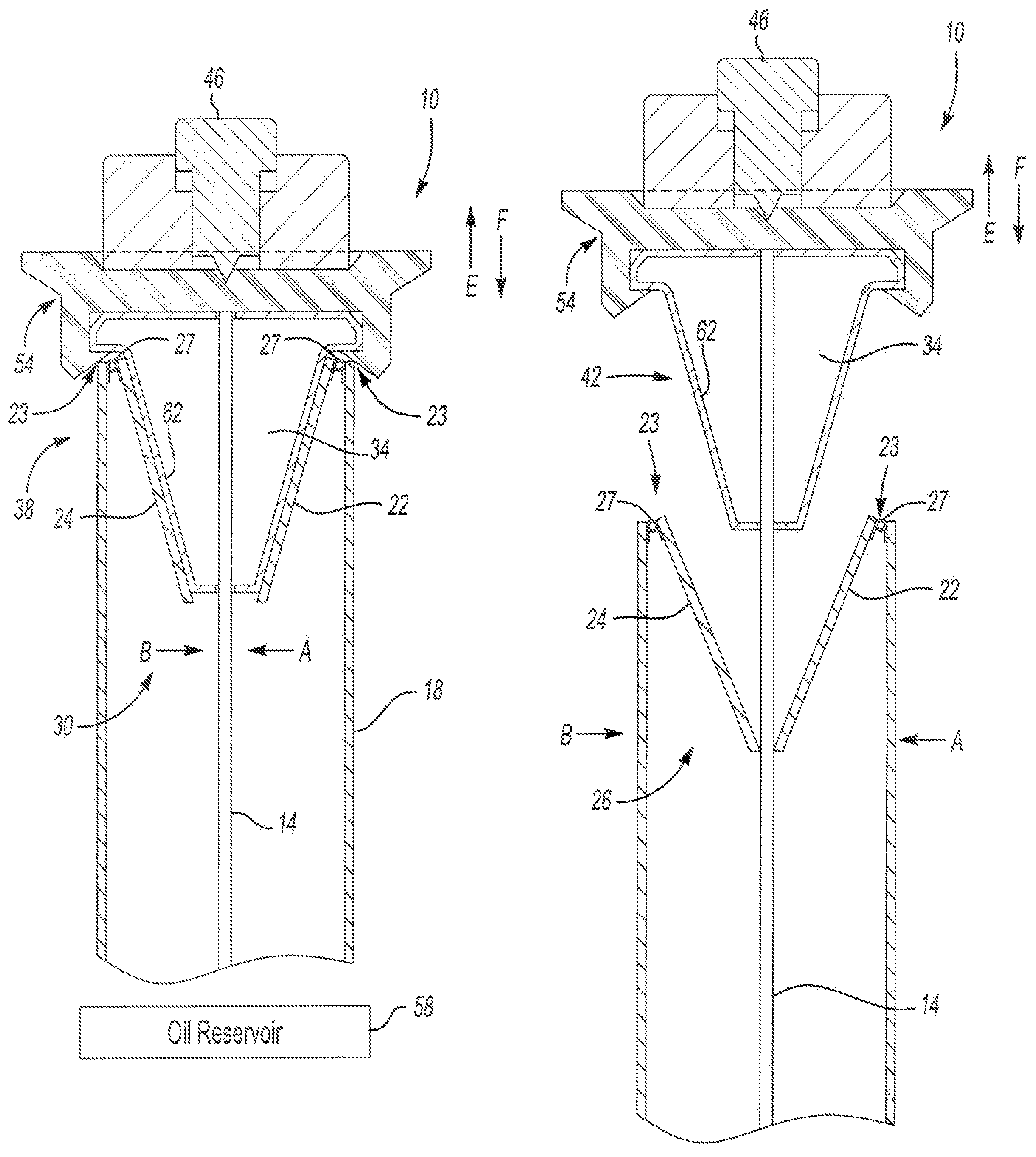
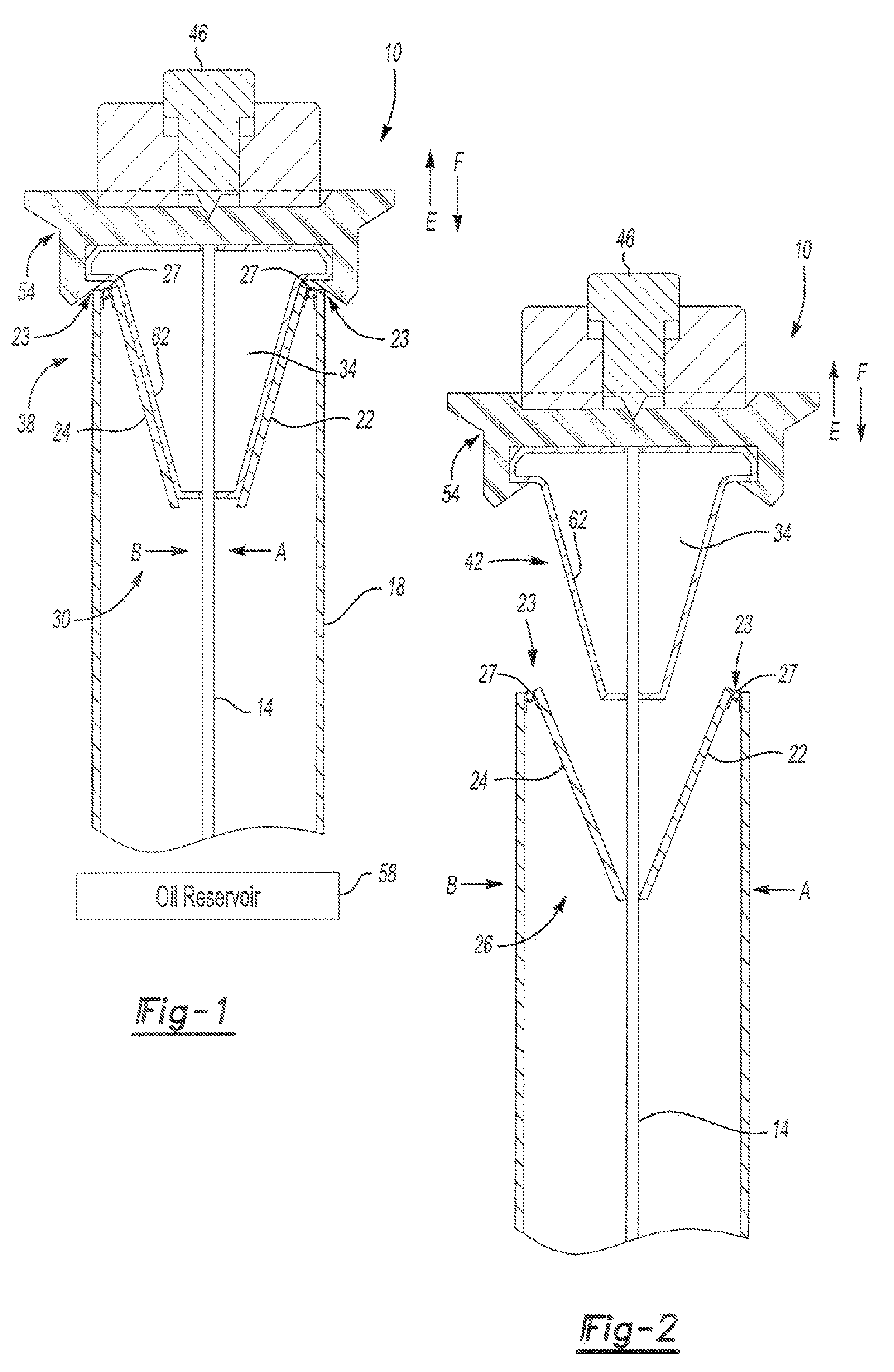
[0023]FIG. 1 illustrates inventive dip stick assembly 10. Dip stick assembly 10 has dip stick 14 disposed in housing 18 as shown. Housing 18 is connected to oil reservoir 58 in a vehicle. Dip stick 14 has markings 15 that permit the fluid level of oil reservoir to be read by dip stick 14 as known.

[0024]In contrast to existing assemblies, dip stick assembly 10 has wipers, such as wipers 22 and 24, which pivot between engaged position 26 as shown in FIG. 2 and disengaged position 30 as shown in FIG. 1. Wipers 22, 24 are connected to housing 18 and are resiliently biased by springs 27 to engaged position 26, which is in contact with dip stick 14 as shown in FIG. 2. Wiper 22 is connected to housing 18 at pivot 23 while wiper 24 is connected to housing 18 at pivot 25. Within pivot 23 and pivot 25 are springs 27 that urge wiper 22 in the direction of arrow A and urge wiper 24 in direction of arrow B when wiper 22 and 24 are in the disengaged position 30 as shown in FIG. 1.

[0025]Maintainin...


PUM


Abstract

A dip stick assembly has a dip stick and a housing that receives the dip stick. A wiper is selectively engageable with the dip stick. The wiper has an engaged position and a disengaged position. In the engaged position, the wiper is in contact with the dip stick. In the disengaged position, the wiper is out of contact with the dip stick. The wiper is resiliently biased into the engaged position with dip stick. A block maintains the wiper in the disengaged position when in a blocking position and permits the wiper to be in the engaged position when in the unblocking position.

Description

BACKGROUND OF THE INVENTION[0001]This invention relates to a dip stick assembly for a vehicle.[0002]A dip stick is used to measure oil in an oil pan or, more broadly, an oil reservoir of a vehicle. Typically, the dip stick remains inserted in a housing that is connected to the oil reservoir. The dip stick will typically have some markings, which serve to reflect the level of oil in the reservoir. During normal operation of the vehicle, oil will splash onto the dip stick at points that do not accurately reflect the oil level. When the oil level is checked, the dip stick is removed from the housing and is typically wiped clean with a cloth. The dip stick is then reinserted into the housing and then removed again to read the oil level, which then provides an accurate reflection of the oil level in the reservoir.[0003]This technique for checking the oil level in a vehicle has its drawbacks. Specifically, the technique is messy. One must have ready some way to wipe the dip stick clean, w...

Claims


Application Information

Patent Timeline
IPC IPC(8): G01F23/04
CPCG01F23/04G01F23/045
Inventor GOLDSTEIN, FREDRICBARTO, JR., ROBERT MURRAY
Owner GROUP ONE
Why Eureka
Try Eureka