
Fluid reservoir assembly

a technology of fluid reservoir and assembly, which is applied in the direction of liquid/fluent solid measurement, engine lubrication, brushes, etc., can solve the problems of messy technique, inconvenient, and inconvenient to use, and achieves simple and inexpensive assembly and technique.

Active Publication Date: 2012-09-25
GROUP ONE
View PDF45 Cites 10 Cited by
  • Summary
  • Abstract
  • Description
  • Claims
  • Application Information

AI Technical Summary

Benefits of technology

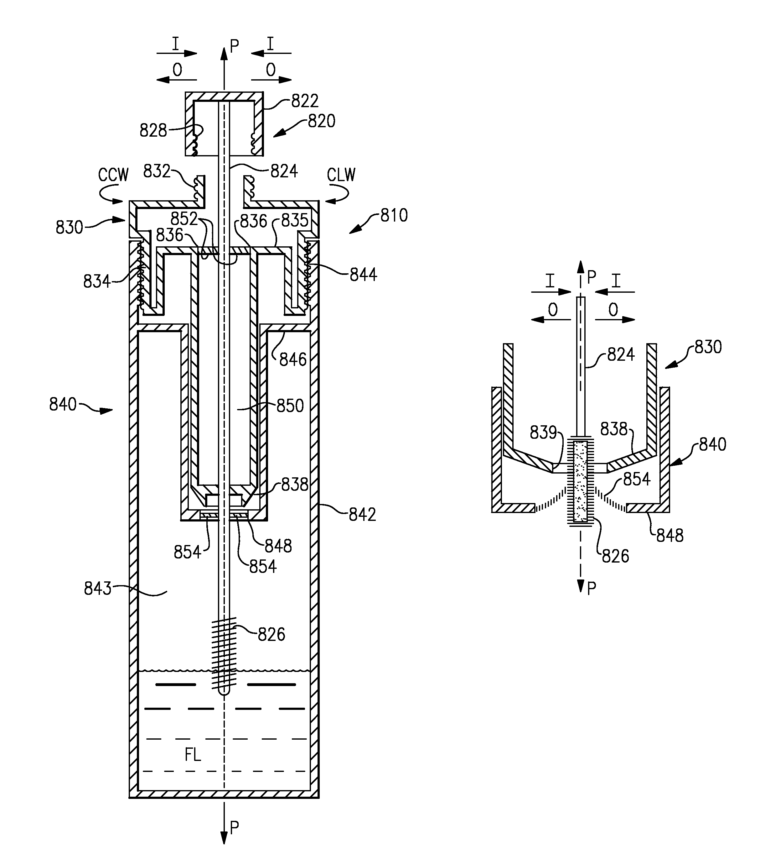
"The invention is about a dip stick assembly and a related technique for cleaning and reading the oil level of an oil reservoir in a vehicle. The dip stick has wipers attached to a housing, which can be moved into an engaged position to wipe the dip stick. The wipers are resiliently biased into the engaged position but can be blocked to prevent them from moving into the engaged position. The block is moveable between a blocking position and an unblocking position. The invention also involves a cosmetic bottle with a wiper for wiping the cosmetic fluid from an applicator, which can be inserted and removed from the bottle. The wiper has two positions and a block is used to selectively allow the wiper to move between the two positions. The invention also includes a fluid reservoir assembly with a seal to prevent air from entering and a second seal to control the amount of fluid wiped from the brush."

Problems solved by technology

Due to the viscosity of fluid, fluid will tend to collect on the inserter and may interfere with the accurate measurement of fluid or the controlled distribution of fluid.
This may be inconvenient, messy as well as wasteful.
Specifically, the technique is messy.
Also, the cloth or such used to wipe the dip stick must be thrown away because it is difficult or impractical to clean, both wasting the cloth and causing the inconvenience of its disposal.
Oil is also wasted because oil on the dip stick is left on the cloth rather than returned to the oil reservoir.
However, these systems are often unreliable or expensive.
Although preferable to wiping the dip stick with a rag, these assemblies may be complicated, awkward to use or expensive.
Because of the viscous nature of the mascara liquid, the brush would exit the bottle fully (and unevenly) loaded with mascara, making it impractical for application to fine eyelashes.
The problem with this system is that a compromise amount of mascara must be determined upon design and production.
The opening is non-adjustable and therefore the user cannot increase or decrease the amount of mascara on the brush.
If the user should desire a larger amount of mascara, it would not be possible to obtain a fully loaded brush with the one-size-fits-all opening.
Nor, if so desired, can the user obtain a lesser amount of mascara on the brush without using a tissue to manually wipe off the brush.
Another problem is that mascara typically coagulates over time and after repeated use, as with air entering the housing, the liquid loses water content, becoming more viscous.
The opening which may have suited new free flowing mascara may no longer suit older thicker mascara and undesired clumps of mascara may remain on the applicator.
However, as a consequence of this design, the user must carry a tissue or other wipe for the applicator, wipe the applicator, and then later dispose of the wipe after its use.
These steps are inconvenient for the user.
Moreover, excess mascara is simply wasted.
Additionally, this older thicker mascara, reduced in volume, may more readily stick to the sides of the housing, making it impossible for the brush to angle to reach it due to the restrictive nature of the plug opening.
The undesired result is an unsatisfactory percentage of mascara remaining beyond the reach of the brush and so requiring the user to dispose of the product before it is actually fully used.
Similar problems exist with other cosmetic fluids, such as lip gloss and nail polish, both of which also employ an applicator which obtains the cosmetic fluid from a bottle.

Method used


Image

  • Fluid reservoir assembly
  • Fluid reservoir assembly
  • Fluid reservoir assembly

Examples


Embodiment Construction

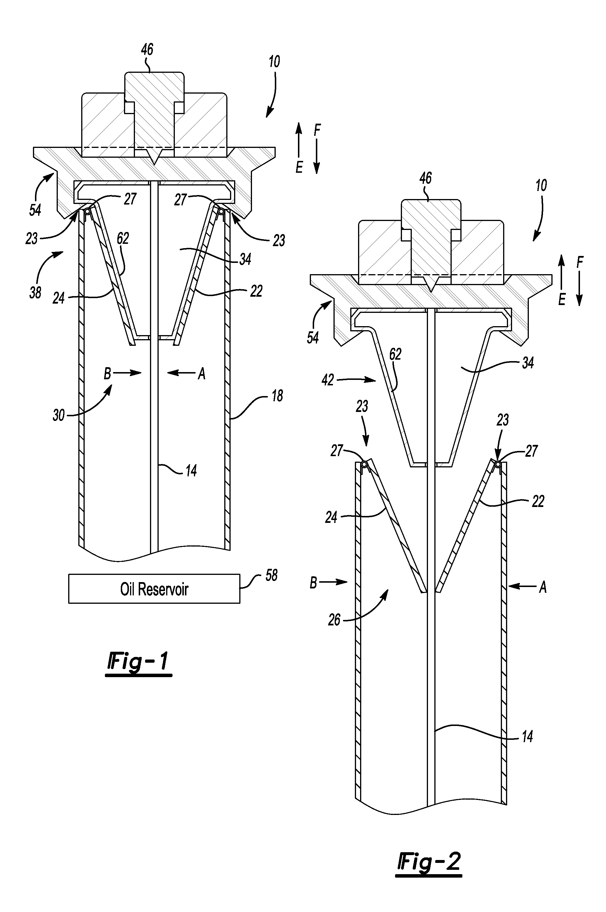
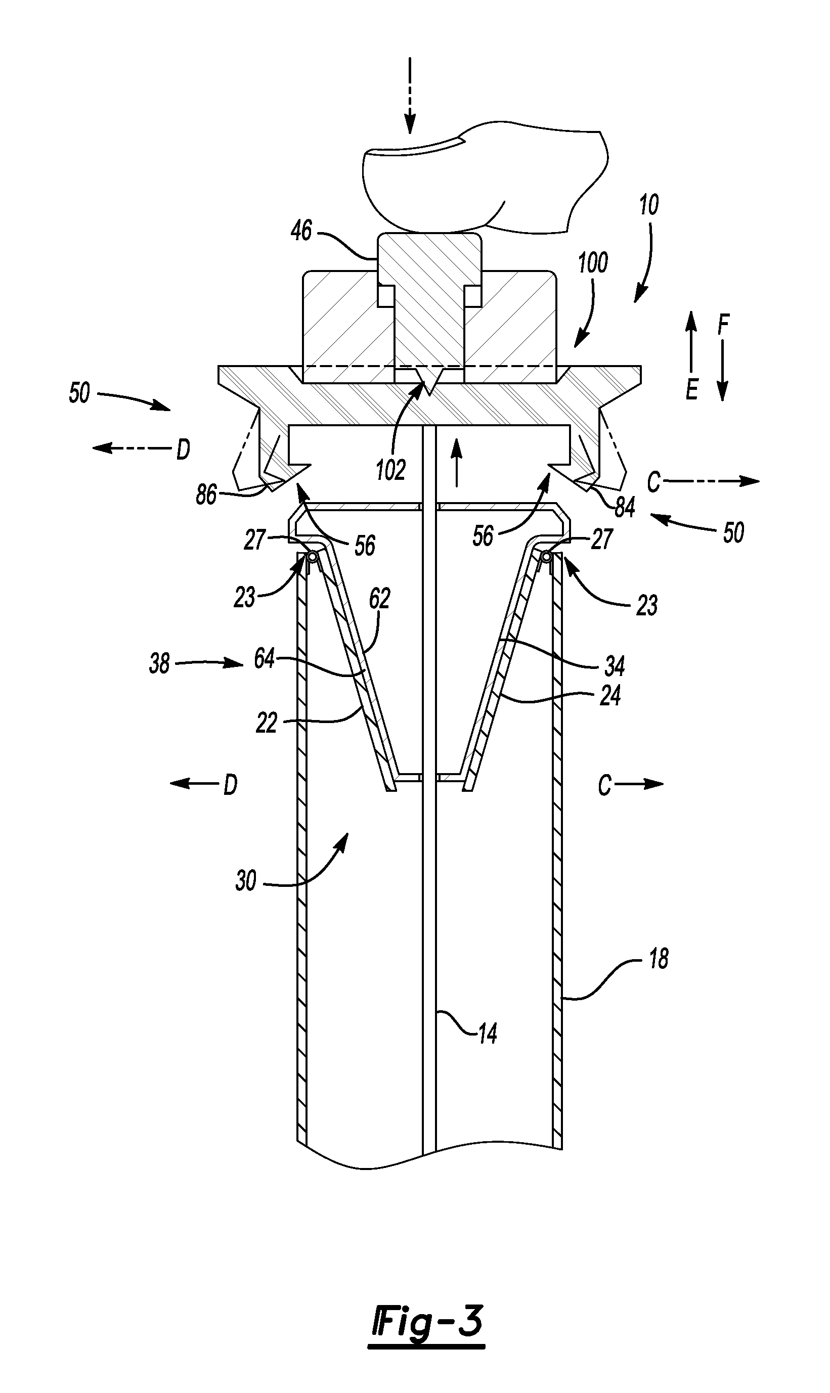
[0066]FIG. 1 illustrates inventive dip stick assembly 10. Dip stick assembly 10 has an inserter, here dip stick 14, disposed in housing 18 as shown. Housing 18 is connected to oil reservoir 58 in a vehicle. Dip stick 14 has markings 15 that permit the fluid level of oil reservoir to be read by dip stick 14 as known.

[0067]In contrast to existing assemblies, dip stick assembly 10 has wipers, such as wipers 22 and 24, which pivot between engaged position 26 as shown in FIG. 2 and disengaged position 30 as shown in FIG. 1. Wipers 22, 24 are connected to housing 18 and are resiliently biased by springs 27 to engaged position 26, which is in contact with dip stick 14 as shown in FIG. 2. Wiper 22 is connected to housing 18 at pivot 23 while wiper 24 is connected to housing 18 at pivot 25. Within pivot 23 and pivot 25 are springs 27 that urge wiper 22 in the direction of arrow A and urge wiper 24 in direction of arrow B when wiper 22 and 24 are in the disengaged position 30 as shown in FIG....


PUM


Abstract

A bottle assembly has a bottle for storing a fluid, such as a cosmetic fluid. An applicator for applying the fluid is configured to be insertable and removable from the bottle along a path. A sealing body, or assembly, which may include one or more seals, is configured to continue to seal the bottle when the cap is removed.

Description

CROSS REFERENCE TO RELATED APPLICATIONS[0001]This application claims priority to U.S. Provisional Application No. 61 / 445,087 filed Feb. 22, 2011, and is also a continuation-in-part of U.S. Non-Provisional application Ser. No. 12 / 949,171 filed Nov. 18, 2010, now U.S Pat. No. 7,979,999 which is a continuation of U.S. Non-Provisional application Ser. No. 12 / 509,547 filed Jul. 27, 2009 (now U.S. Pat. No. 7,837,402), which is a continuation of U.S. Non-Provisional application Ser. No. 12 / 053,815 filed on Mar. 24, 2008 (now U.S. Pat. No. 7,578,071), which is a continuation-in-part to U.S. Non-Provisional application Ser. No. 11 / 553,644 filed on Oct. 27, 2006 (now U.S. Pat. No. 7,360,319).BACKGROUND OF THE INVENTION[0002]This invention relates to a fluid reservoir having a wiper (or, “membrane” or “seal”).[0003]A commercial fluid container has a fluid reservoir for storing a fluid. There may be an inserter provided with the fluid container to check its fluid level in the case of an oil res...

Claims


Application Information

Patent Timeline
Patent Type & Authority Patents(United States)
IPC IPC(8): G01F23/04A46B17/06
CPCG01F23/045G01F23/04A45D40/267A45D40/268
Inventor GOLDSTEIN, FREDRICBARTO, JR., ROBERT MURRAY
Owner GROUP ONE
Learn More