Object tracking and eye state identification method
What is Al technical title?
Al technical title is built by PatSnap Al team. It summarizes the technical point description of the patent document.
a tracking method and eye state technology, applied in the field of object tracking method, can solve the problems of poor performance under real-world imaging conditions, degenerate accuracy of eye template, etc., and achieve the effect of reducing the euclidian spatial distan
Active Publication Date: 2008-04-22
APTIV TECH LTD
View PDF9 Cites 27 Cited by
Summary
Abstract
Description
Claims
Application Information
AI Technical Summary
This helps you quickly interpret patents by identifying the three key elements:
Problems solved by technology
Method used
Benefits of technology
[0004]The present invention is directed to an improved object tracking method that tracks a target object between successively generated infrared video images using an optimized grey-scale hat filter to extract the target object from the background. The filtered image is binarized, and candidate binary blobs are extracted. The binary blob that minimizes the Euclidian spatial distance to the previous position of the object and satisfies a specified appearance model is selected, and its center of mass is taken as the current position of the object. Where the object is a person's eye, the eye state is determined by analyzing the shape and appearance of the binary blob along with changes in its size and the previous eye state, and applying corresponding parameters to an eye state decision matrix. The decision matrix also indicates a confidence in the eye state determination.
Problems solved by technology
While eye location and tracking algorithms can work reasonably well in a controlled environment, they tend to perform poorly under real world imaging conditions, particularly in systems having only one camera.
While this technique is useful, the accuracy of the eye template tends to degenerate over time due to drift and conditions such as out-of-plane rotation of the subject's head, noise and changes in the eye appearance (due to glasses, for example).
Method used
Image
Click on the blue label to locate the original text in one second.
Reading with bidirectional positioning of images and text.
Examples
Embodiment Construction
[0011]The object tracking method of the present invention is disclosed in the context of a system that tracks and monitors the eye of a motor vehicle driver, and additionally determines whether the eye is open or closed. However, it will be recognized that the disclosed tracking method is equally applicable to other vision systems that track the location of an object, whether animate or inanimate.
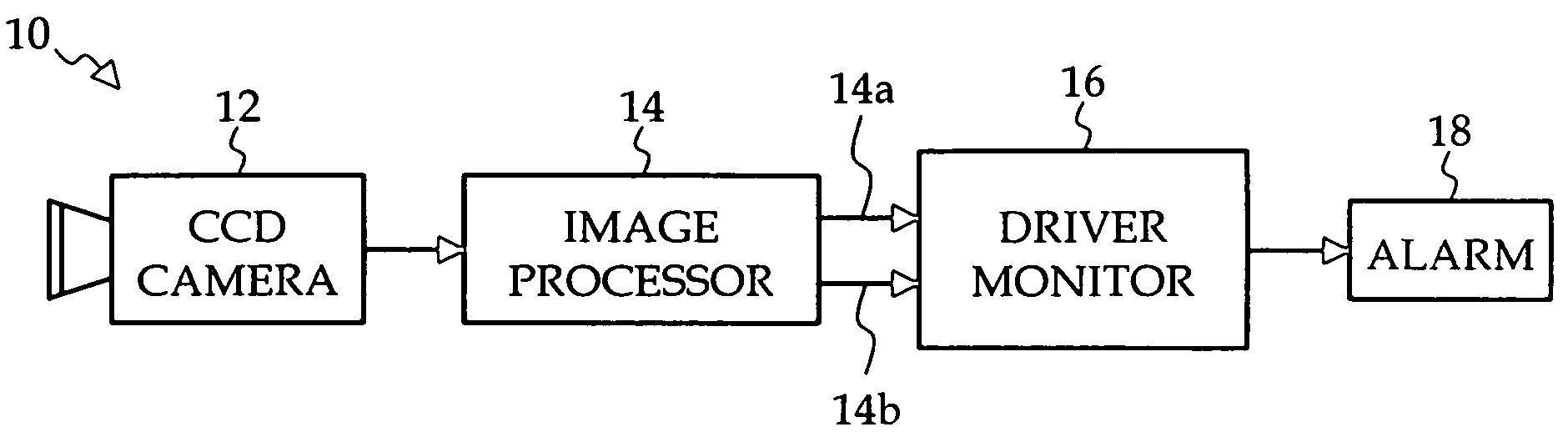
[0012]Referring to the drawings, and particularly to FIG. 1, the reference numeral 10 generally designates a motor vehicle vision system for monitoring driver alertness. The system 10 includes an infrared CCD camera 12, a microprocessor-based image processor 14, a driver monitor 16, and an alarm 18. The camera 12 is mounted in a convenient location within the vehicle passenger compartment, such as in a center console or instrument panel, and is configured to produce an unobstructed image of the driver's head, taking into account differences in driver height and orientation. The image proces...
PUM
Abstract
An object tracking method tracks a target object between successively generated infrared video images using a grey-scale hat filter to extract the target object from the background. The filtered image is binarized, and candidate binary blobs are extracted. The binary blob that minimizes the Euclidian spatial distance to the previous position of the object and satisfies a specified appearance model is selected, and its center of mass is taken as the current position of the object. Where the object is a person's eye, the eye state and decision confidence are determined by analyzing the shape and appearance of the binary blob along with changes in its size and the previous eye state, and applying corresponding parameters to an eye state decision matrix.
Description
TECHNICAL FIELD[0001]The present invention relates to an object tracking method for tracking the location of an object in successively generated frames of a video image, and where the object is a person's eye, for identifying the eye state as open or closed.BACKGROUND OF THE INVENTION[0002]Vision systems frequently entail locating and tracking an object such as a person's eye in successively generated frames of video data. In the motor vehicle environment, for example, a CCD camera can be used to generate a video image of the driver's face, and portions of the image corresponding to the driver's eyes can be analyzed to assess driver gaze or drowsiness. See, for example, the U.S. Pat. Nos. 5,795,306; 5,878,156; 5,926,251; 6,097,295; 6,130,617; 6,243,015; 6,304,187; and 6,571,002, incorporated herein by reference. While eye location and tracking algorithms can work reasonably well in a controlled environment, they tend to perform poorly under real world imaging conditions, particularl...
Claims
Application Information
Patent Timeline
Application Date:The date an application was filed.
Publication Date:The date a patent or application was officially published.
First Publication Date:The earliest publication date of a patent with the same application number.
Issue Date:Publication date of the patent grant document.
PCT Entry Date:The Entry date of PCT National Phase.
Estimated Expiry Date:The statutory expiry date of a patent right according to the Patent Law, and it is the longest term of protection that the patent right can achieve without the termination of the patent right due to other reasons(Term extension factor has been taken into account ).
Invalid Date:Actual expiry date is based on effective date or publication date of legal transaction data of invalid patent.