
Gantry with auto-adjusting prestressing

a prestressing and gantry technology, applied in the field of gantry, can solve the problems of reducing the generalization of the use of the gantry, affecting the construction speed, and consuming a lot of time and money, and achieving the effects of reducing the mid-span deflection, reducing the flexural moments on the main structure, and reducing the loss of prestressing

Active Publication Date: 2008-04-29
PACHECO PEDRO LVARES RIBEIRO DO CARMO
View PDF6 Cites 1 Cited by
  • Summary
  • Abstract
  • Description
  • Claims
  • Application Information

AI Technical Summary

Benefits of technology

"The present invention provides a gantry for use in the construction process of bridges and other structures. The gantry includes a main load bearing structure and at least one unbonded cable. The unbonded cable is either internal or external to the main structure and can be either internal or external to the main load bearing structure. The gantry also includes at least one sensor that measures a physical variation in the main structure and an electronic interface that converts the sensor's measurements into readable data. The data is transmitted to a controller that can activate the unbonded cable to adjust its tension in response to the sensor's readings. The invention allows for the application of large amounts of prestressing without causing undesirable deformations in the main structure when exterior loads are not applied."

Problems solved by technology

However, the factor that hinders their more generalized use is the fact that they represent a large investment in terms of materials and construction labour.
This adaptation is in itself a very time consuming and expensive process which normally delays the pace of construction.
The use of prior art gantries also implies some considerable risk.
This is because they are structures that are meant to support a great deal of permanent and variable loads and can lead to a great deal of deformations and stresses that weaken the structure and may eventually lead to its collapse.
Several accidents have occurred in the past.
However, these structures required the introduction of external tools to increase or decrease the tension of the cables.

Method used


Image

  • Gantry with auto-adjusting prestressing
  • Gantry with auto-adjusting prestressing
  • Gantry with auto-adjusting prestressing

Examples


Embodiment Construction

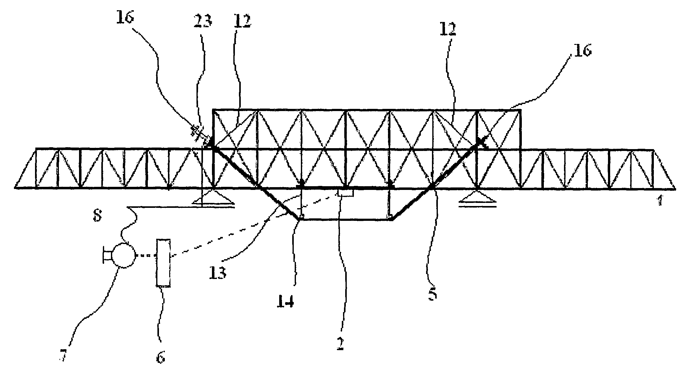
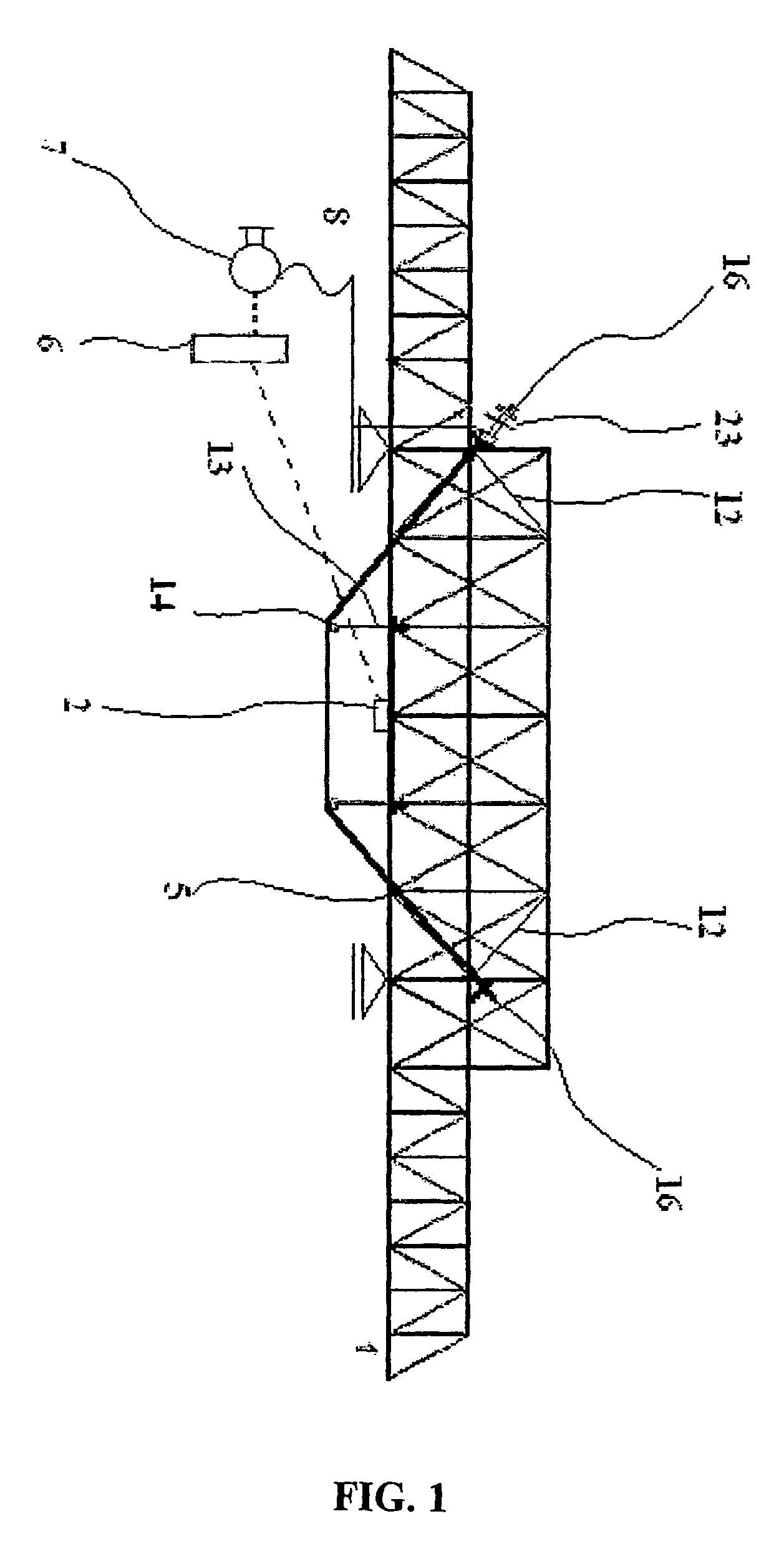
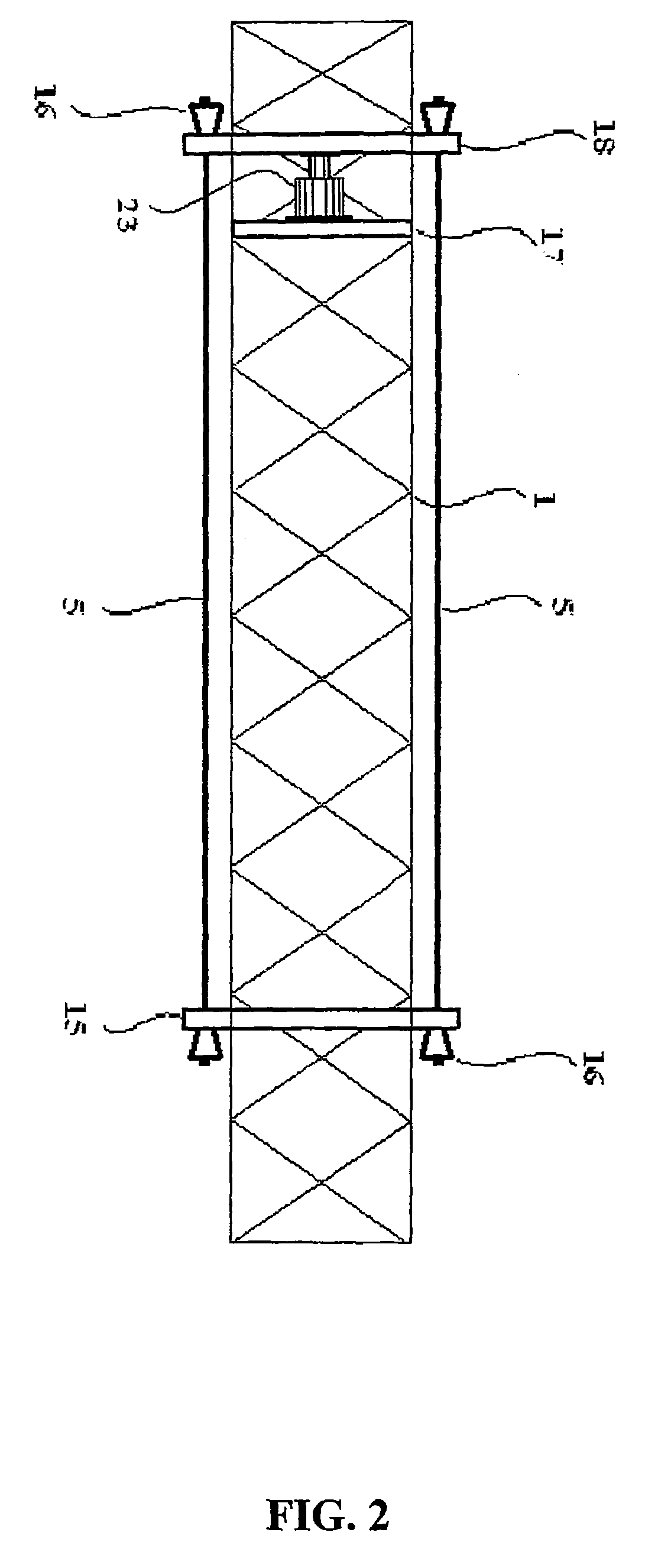
[0033]A detailed description of the invention will now follow making reference to a particular preferred embodiment and the drawings mentioned above. The description of the embodiment and the drawings are only by way of example, and should not be interpreted as limiting the scope of the invention as defined in the attached claims.

[0034]Making reference to FIG. 1, there is provided a gantry comprising a main structure (1) constituted by two outer sections and one middle section. The two outer sections, which are meant to facilitate launching process, are lower in height than the middle section which is intended to support formwork and main loadings. The main structure is a trussed box girder so as to assume a design similar to that illustrated in FIG. 1. The location of the supports are defined for a typical construtive technique where each concrete filling segment, having the same length of the structure's span, starts at a distance of approximately ⅕ of the span from the front supp...


PUM


Abstract

A gantry to be used in the construction process of bridges, viaducts and other structures, which is equipped with a system that automatically adjusts the prestressing of the gantry's structure in accordance to the external actions being applied on it when loadings occur. The adjustment of the prestressing is achieved through the use of at least one sensor (2) that monitors the structure and which sends the measurements taken to a controller (6), . This controller is then capable of activating at least one actuator which alters the tension of the structure's prestressing cable or cables. Amongst the many advantages of the present invention, one is the possibility of applying a large amount of prestressing without this implying undesirable deformations in the main structure (1) when exterior loads are not applied.

Description

TECHNICAL FIELD [0001]This invention relates to a gantry for use in construction, and more specifically to a gantry equipped with a system that automatically adjusts it's prestressing.BACKGROUND ART [0002]In modern civil engineering, the use of gantries (overslung and underslung) in the construction of bridges and viaducts has largely overtaken ground resting scaffolding. However, the factor that hinders their more generalized use is the fact that they represent a large investment in terms of materials and construction labour. Although present gantries are reusable, it is also very common for them to require re-adaptation, in particular when the project calls for it to carry more load then it was initially designed for. This adaptation is in itself a very time consuming and expensive process which normally delays the pace of construction.[0003]The use of prior art gantries also implies some considerable risk. This is because they are structures that are meant to support a great deal...

Claims


Application Information

Patent Timeline
Patent Type & Authority Patents(United States)
IPC IPC(8): G01C9/00E01D21/00
CPCE01D21/00B66C1/00
Inventor PACHECO, PEDRO LVARES RIBEIRO DO CARMO
Owner PACHECO PEDRO LVARES RIBEIRO DO CARMO
Learn More