Child-proof lock assembly

a technology for locking assemblies and children, applied in the field of child-proof lock assemblies, can solve the problems of a dangerous position of the shoulder seat belt at the child's neck, many standard vehicle restraint systems do not adequately protect children from injury,

Inactive Publication Date: 2008-05-06
DILDAY MARLENE A
View PDF10 Cites 24 Cited by
  • Summary
  • Abstract
  • Description
  • Claims
  • Application Information

AI Technical Summary

Benefits of technology

[0016]Each of the base sections includes a plurality of cavities formed in the linear medial edges thereof and each further includes a plurality of window openings formed in the bottom surfaces respectively. The arms are telescopically inserted through the cavities and along a linear path defined orthogonal to the longitudinal lengths of the first and second harnesses wherein the flanged distal ends of the arms become seated within the window openings when the first and second locks are fully engaged to the locked position. The flanged distal ends of the arms may be visible from the bottom surface of the base sections and are resiliently adaptable towards the top surfaces of the base sections respectively for effectively releasing the arms from the cavities and thereby unlocking the first and second locks. The top flaps are pivotal to an unfolded position while the arms are nested within the cavities.

Problems solved by technology

It is well-known that many standard vehicle restraint systems do not adequately protect children from injury during vehicle collisions.
For example, shoulder seat belts often do not adjust sufficiently to accommodate a child, sometimes resulting in the shoulder seat belt being dangerously positioned at the child's neck.
Unfortunately, because the clip slides easily to adjust to the size of the child, an active toddler may soon discover that he or she can slide the clip down, slip the harness straps from his or her shoulders, and climb out of the car seat.

Method used


Image

  • Child-proof lock assembly
  • Child-proof lock assembly
  • Child-proof lock assembly

Examples


Embodiment Construction

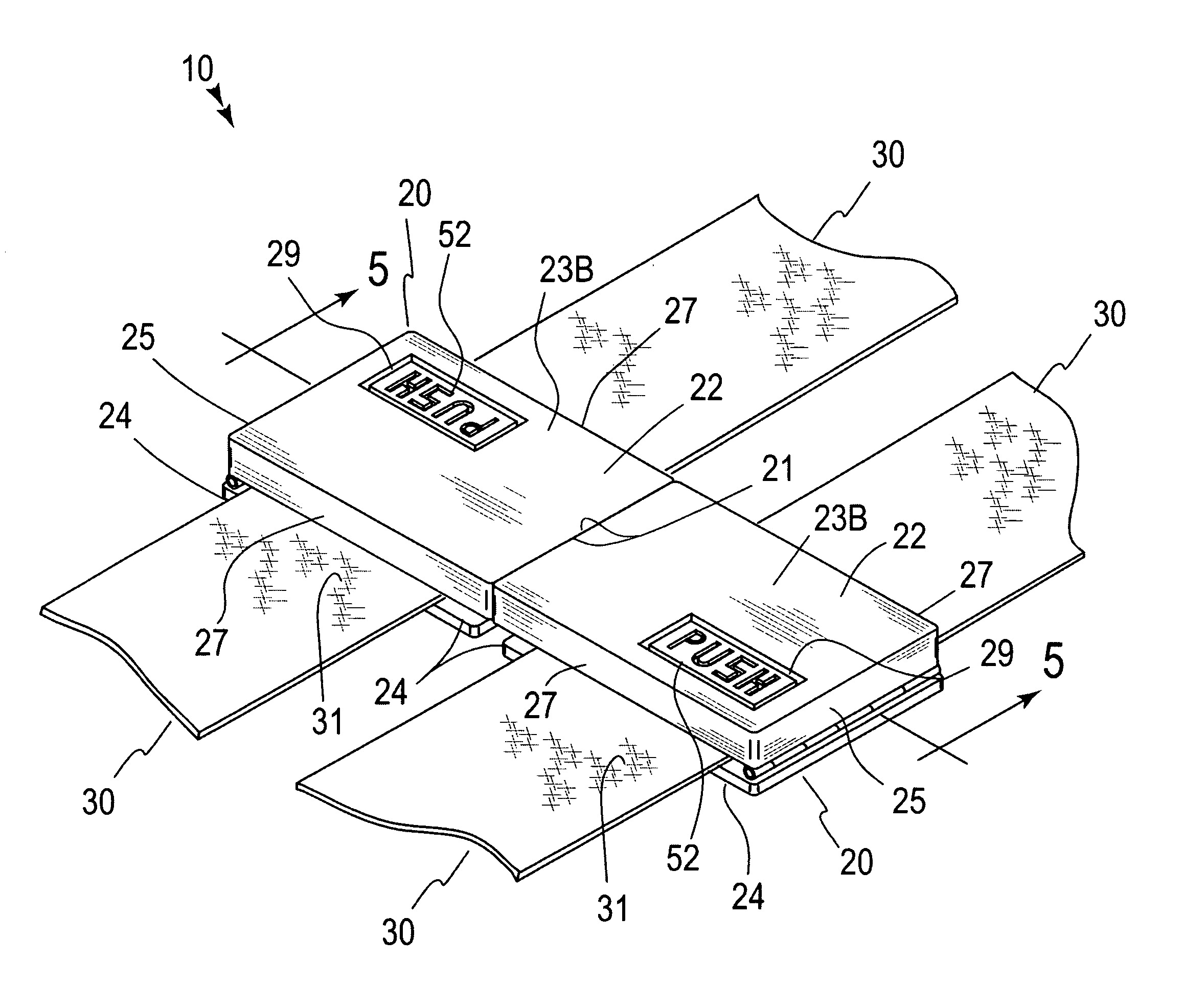
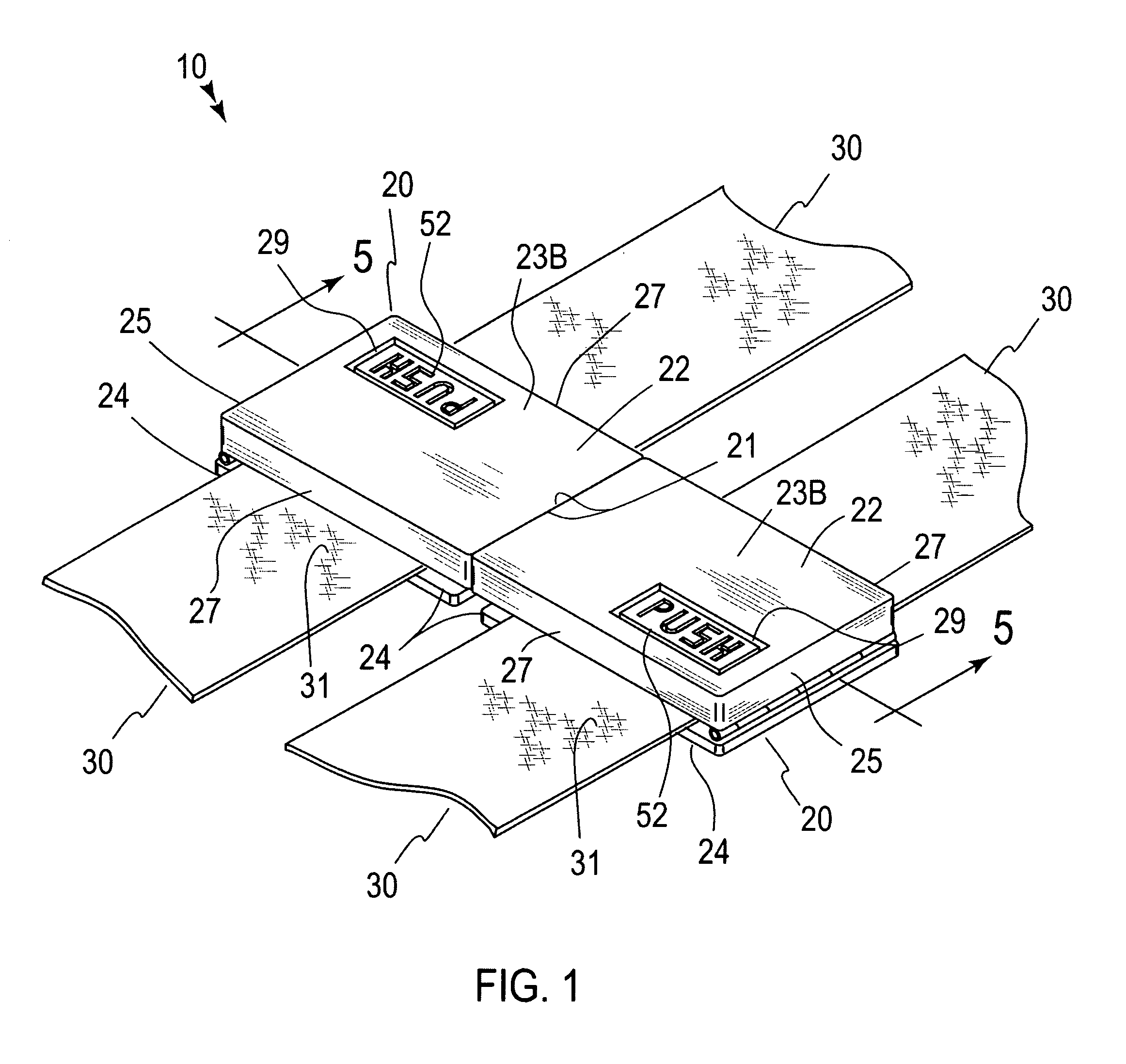
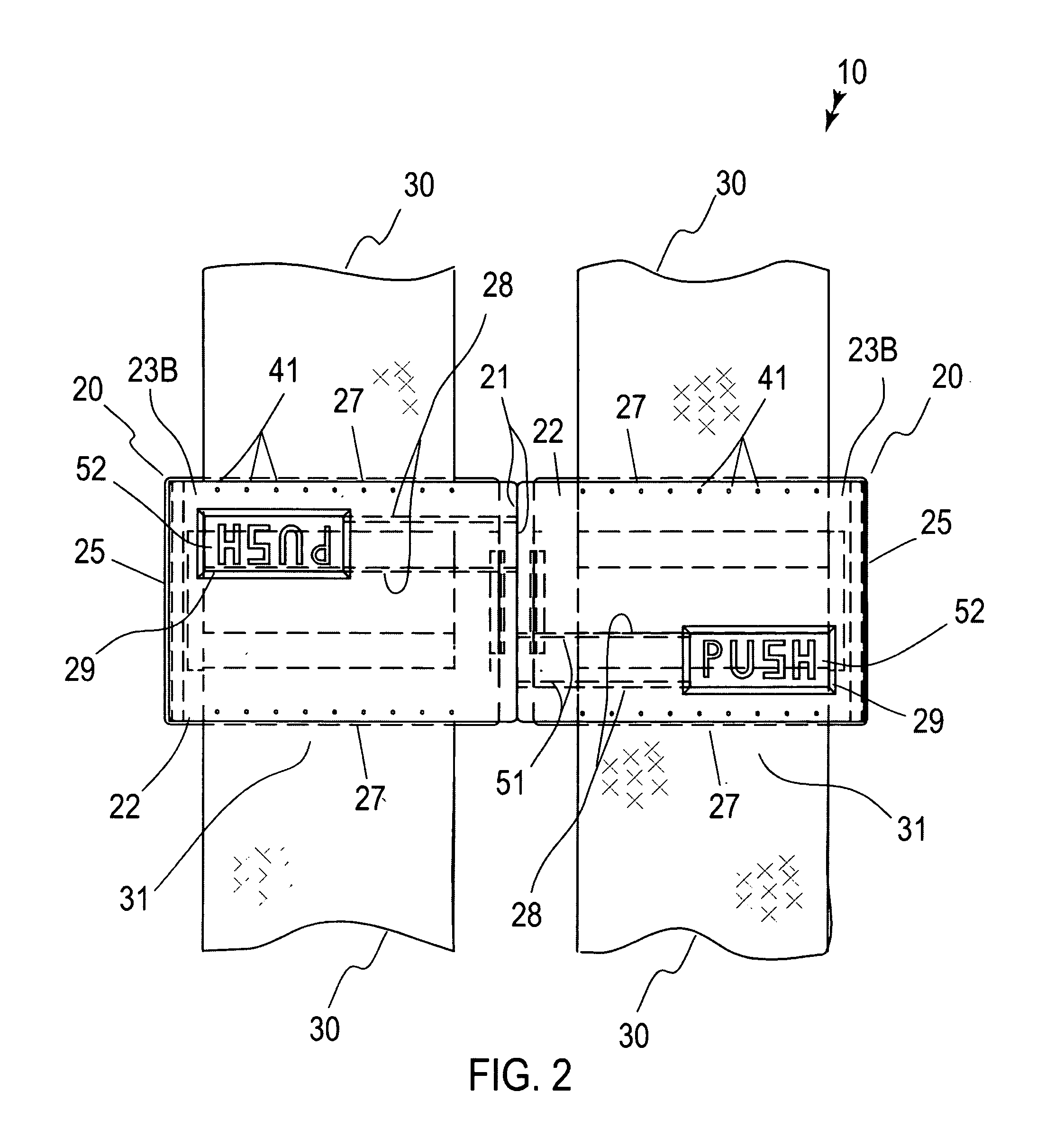
[0025]The present invention will now be described more fully hereinafter with reference to the accompanying drawings, in which a preferred embodiment of the invention is shown. This invention may, however, be embodied in many different forms and should not be construed as limited to the embodiment set forth herein. Rather, this embodiment is provided so that this application will be thorough and complete, and will fully convey the true scope of the invention to those skilled in the art. Like numbers refer to like elements throughout the figures.

[0026]The assembly of this invention is referred to generally in FIGS. 1-5 by the reference numeral 10 and is intended to provide a child-proof lock assembly. It should be understood that the assembly 10 may be used to lock many different types of harnesses and should not be limited in use to only the restraining harnesses of infant and toddler car seats.

[0027]Referring initially to FIGS. 1 through 5, the assembly 10 includes first and second...


PUM


Abstract

A lock and harness assembly includes first and second locks removably attached to each other. The locks are coextensively shaped, and are independently and simultaneously pivotal between folded and unfolded positions. Each lock has a linear medial edge conjoined to the other's medial edge when the locks are at a locked position. First and second harnesses traverse through the first and second locks. The harnesses are slidably positioned through the locks. Each lock includes a mechanism for statically holding the harnesses at a locked position such that the harnesses are prohibited from sliding through the locks after the locks have been coupled. Each lock includes a mechanism for releasably coupling the locks to each other such that the locks must be slidably adapted along a linear path defined orthogonal to the harnesses.

Description

CROSS REFERENCE TO RELATED APPLICATIONS[0001]Not Applicable.STATEMENT REGARDING FEDERALLY SPONSORED RESEARCH OR DEVELOPMENT[0002]Not Applicable.REFERENCE TO A MICROFICHE APPENDIX[0003]Not Applicable.BACKGROUND OF THE INVENTION[0004]1. Technical Field[0005]This invention relates to lock assemblies and, more particularly, to a child-proof lock assembly for a child vehicle car seat.[0006]2. Prior Art[0007]It is well-known that many standard vehicle restraint systems do not adequately protect children from injury during vehicle collisions. For example, shoulder seat belts often do not adjust sufficiently to accommodate a child, sometimes resulting in the shoulder seat belt being dangerously positioned at the child's neck. To remedy this problem, supplemental child vehicle restraints, such as child car seats, have become an increasingly popular way of properly restraining children during vehicle collisions, thereby reducing injuries resulting therefrom. Instead of the conventional should...

Claims


Application Information

Patent Timeline
Patent Type & Authority Patents(United States)
IPC IPC(8): A44B11/25
CPCA44B11/25A44D2200/12Y10T24/45194Y10T24/45529Y10S24/38
Inventor DILDAY, MARLENE A.
Owner DILDAY MARLENE A
Why Eureka
Try Eureka