Putter head

a technology of putter head and putter head, which is applied in the field of putter head, can solve problems such as damage to the image of the golfer, and achieve the effects of preventing the golfer, facilitating the position of a sweet spot, and gently and reliably putting

Inactive Publication Date: 2008-05-13
TAO TADAMASA
View PDF31 Cites 60 Cited by
  • Summary
  • Abstract
  • Description
  • Claims
  • Application Information

AI Technical Summary

Benefits of technology

[0035](1) According to the present invention, the blurring marks have profile lines arranged substantially symmetrically and non-parallel with respect to the longitudinal line mark with a lateral gap between the blurring lines and the strip-like longitudinal line mark. Accordingly, although the strip-like longitudinal line mark is necessary to align the putter head with the imaginary ball hitting line at the address position, in the stroking operation of the putter head, due to the provision of the symmetrical and non-parallel blurring marks, the blurring marks attract more attention of a golfer than the strip-like longitudinal line mark during the stroking of the putter head and hence, the longitudinal line mark becomes less conspicuous during the stroking of the putter head. Further, the profile of one blurring mark is arranged approximately parallel to the imaginary ball hitting line at a take-back position and the profile line of another blurring mark is arranged approximately parallel to the imaginary ball hitting line at a follow-through position. Accordingly, a golfer hardly feels the change of the inclination of the longitudinal line mark whereby the putter head can give a sense of smooth and comfortable stroking to the golfer.
[0036](2) With the provision of the background mark, without being influenced by the color of the putter head body, due to the combination of two colors applied to the background mark and the longitudinal line mark and the blurring marks, it is possible to make both of the longitudinal line mark and the blurring marks conspicuous and hence, it is possible to prevent the golfer from having the feeling that the background mark is arcuately swinging during the putting operation.
[0037](3) Further, by making the blurring marks conspicuous, the golfer can easily feel a position of a sweet spot during the putting operation. Particularly, in the constitution in which the width between the blurring marks is gradually narrowed toward the sweet spot from the rear portion of the putter head body where the width between the blurring marks is wide, the golfer's eyes are focused on the sweet spot and hence, it is possible to allow the golfer to concentrate on putting.
[0038](4) Further, by allowing the blurring marks to have a chevron shape in which the width between the blurring marks is gradually increased from a rear end to a front end of the putter head body, the blurring marks wrap the ball in the vicinity of the sweet spot and hence, the golfer can gently and reliably perform the putting.BRIEF DESCRIPTION OF THE SEVERAL VIEWS OF THE DRAWING
[0039]FIG. 1 is an explanatory view of a first embodiment showing a trajectory of stroking of a putter head shown in FIG. 22;
[0040]FIG. 2 is an explanatory view of a second embodiment showing a trajectory of stroking of a putter head shown in FIG. 33;

Problems solved by technology

Accordingly, the golfer strongly feels the arcuate swinging of the putter head on the horizontal plane due to the inclination and this feeling damages his / her image to perform the stroke parallel to the imaginary ball hitting line direction.

Method used


Image

  • Putter head
  • Putter head
  • Putter head

Examples


first embodiment

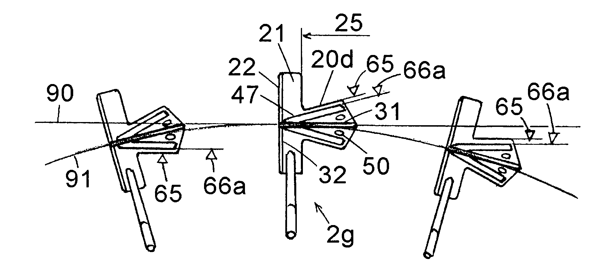
[0082]FIG. 1 is an explanatory view of a first embodiment showing a trajectory of stroking of a putter head 2g shown in FIG. 22.

[0083]Although the constitution of the putter head 2g is explained in detail in conjunction with FIG. 22, in this embodiment, the respective directions of profile lines 65 of a fan-shaped projecting portion 20a on a back-surface side of a putter head body and profile lines 66a of V-shaped blurring marks 47 formed on an upper surface of the putter head body are arranged to take an oblique posture with respect to an imaginary ball hitting line direction 90 or a strip-like longitudinal line mark 31 which is overlapped to the imaginary ball hitting line direction 90 at an address position. On the other hand, in a take-back position and a follow-through position, as shown in FIG. 1, the profile line 66a of one V-shaped blurring mark 47 is arranged approximately parallel to the imaginary ball hitting line direction 90 at a take-back position and the profile line ...

second embodiment

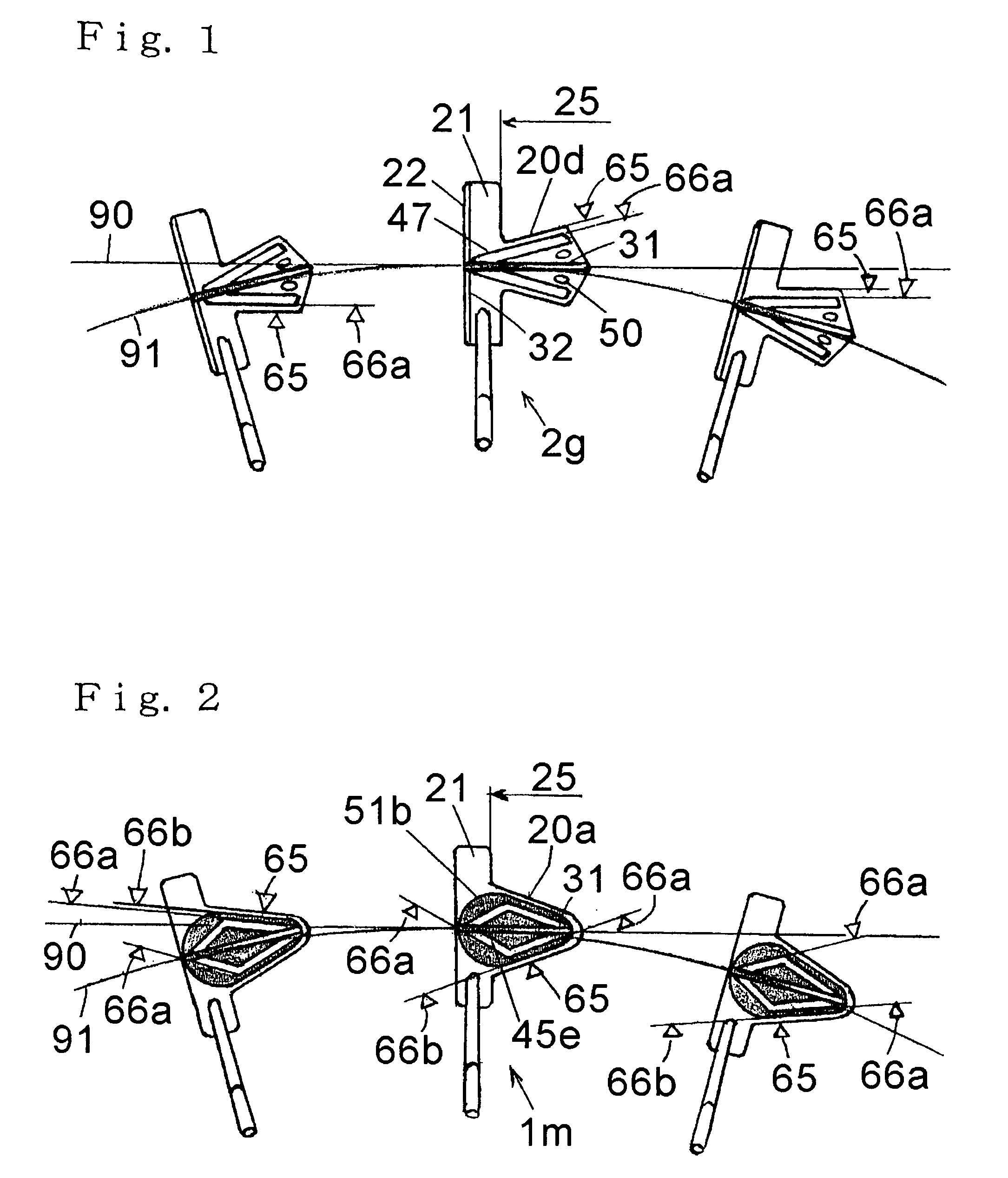
[0086]FIG. 2 is an explanatory view of a second embodiment showing a trajectory of stroking of a putter head 1m shown in FIG. 33.

[0087]Although the constitution of the putter head 1m is explained in detail in conjunction with FIG. 33, in this embodiment, the respective directions of profile lines 65 of a mountain-shaped projecting portion 20a on a back-surface side of a putter head body, profile lines 66b of a fan-shaped background mark 51b, and profile lines 66a of modified rhombic ring-like mark which is formed inside the background mark 51b and is constituted of a pair of blurring marks 45e which are arranged to take an oblique posture with respect to an imaginary ball hitting line direction 90 at an address position. On the other hand, in a take-back position and a follow-through position, as shown in FIG. 2, the profile line 66a of one blurring mark 45e is arranged approximately parallel to the imaginary ball hitting line direction 90 at a take-back position and the profile lin...

embodiment 3

[0089]With respect to a putter head 2a shown in FIG. 6, a profile shape of an upper surface 21 of a projecting portion 20b which is integrally formed on a back surface side 25 of a putter head body 12a and extends from a back surface 26 of the putter head body 12a has a width thereof increased in the rearward direction and has a semi-circular fan-shaped end portion. Here, the projecting portion 20b forms a portion of the putter head body 12a. Further, the projecting portion 20b is connected with one end 26 of the back surface of the putter head body 12a with a lateral width of 30b. An imaginary line axis 24 is defined on upper surfaces of the putter head body 12a and the projecting portion 20b and extends rearwardly from a center (a sweet spot) 23 of the putter face 22 in the direction orthogonal to the putter face 22. In this embodiment, although not shown in the drawing, a longitudinal line mark having a given width is formed on the upper surface and putter head body 12a and the p...


PUM


Abstract

The present invention provides a putter head which includes a putter head body which has a portion thereof connected to a distal end of a putter shaft; a laterally extending putter face which is formed on a front portion of the putter head body; a strip-like longitudinal line mark which is capable of being aligned with an imaginary ball hitting line at an address position, the longitudinal line mark being formed on an upper surface of the putter head body and extending rearwardly from a center of the putter face in the direction orthogonal to the putter face; and blurring marks which are formed on the upper surface of the putter head body in a state that the blurring marks sandwich the longitudinal line mark, the blurring marks having profile lines which are arranged substantially symmetrically and non-parallel with respect to the longitudinal line mark, wherein the profile of one blurring mark is arranged approximately parallel to the imaginary ball hitting line at a take-back position and the profile line of another blurring mark is arranged approximately parallel to the imaginary ball hitting line at a follow-through position.

Description

CROSS-REFERENCES TO RELATED APPLICATIONS[0001]The disclosure of Japanese Patent Application JP2004-171984 filed on Jun. 10, 2004 and Japanese Patent Application JP2005-080824 filed on Mar. 22, 2005 including the specifications, the drawings and abstracts are incorporated herein by reference in its entirety.BACKGROUND OF THE INVENTION[0002]1. Field of the Invention[0003]The present invention relates to a putter head which gives a sense of smooth and comfortable stroking to a golfer while allowing the golfer to hit a golf ball so that the golf ball accurately travel on an imaginary ball hitting line direction.[0004]2. Description of the Related Art[0005]FIG. 3 shows one type of conventionally known putter. As shown in FIG. 3, the putter includes a grip portion 99b which is adapted to be grasped by a golfer, a shaft 100 extending linearly downward from the grip portion 99b, and a putter head 99 which is connected to a distal end of the shaft 100. The putter head 99 has a laterally exte...

Claims


Application Information

Patent Timeline
Patent Type & Authority Patents(United States)
IPC IPC(8): A63B69/36
CPCA63B53/0487A63B59/0088A63B2053/0437A63B2053/0433A63B2053/0441A63B53/0433A63B53/0437A63B53/0441A63B60/50
Inventor TAO, TADAMASA
Owner TAO TADAMASA
Why Eureka
Try Eureka