Method for interacting a pointing device with a target point arranged on a projection screen of a virtual desktop and pointing device therefore

a pointing device and target point technology, applied in the direction of user-computer interaction input/output, instruments, electric digital data processing, etc., can solve the problems of social acceptance problems, user discomfort, user physical movements of users of such pointing devices, etc., and achieve the effect of simple body movements and less conspicuous movements

Active Publication Date: 2019-10-31
RODE OLIVER HORST
View PDF0 Cites 0 Cited by
  • Summary
  • Abstract
  • Description
  • Claims
  • Application Information

AI Technical Summary

Benefits of technology

[0004]The system described herein includes providing a method for interacting a pointing device with a target point arranged on a projection surface of a virtual desktop and a pointing device set up for this purpose, which overcomes these disadvantages of the state of the art. The interaction should be possible in a less conspicuous way and with simple body movements.
[0006]In this way, the interaction of the pointing device with the target point may be effected by means of a simple, essentially two-dimensional carrier medium on which a machine-readable two-dimensional code may be applied and which may be aligned in such a way by means of simple hand movements by translatory displacement along an axis parallel to the carrier plane and by rotational tilting about a tilting axis The tip of a vector whose spatial orientation may be determined by the normal vector determined in the first method step in the area center of gravity of the surface occupied by the code, and whose tip (and thus also whose length from the starting point) may be determined by the target point to be controlled and thus predetermined on the projection surface, may point to the target point to be controlled and coincides therewith. By means of an additional gesture movement in the form of a rotational movement of the carrier plane about an axis of rotation perpendicular to the carrier plane, an activation signal of the pointing device may be generated.
[0007]This additional gesture movement may be carried out with the same hand and from the same sequence of movements as the alignment of the carrier plane to the target point provided for in the first process step. Both movement sequences may be realized by anyone by using their wrist without special difficulties and further physical activities. The operation of the pointing device and thus the interaction with the target point may be possible in a much simpler way compared to the previous state of the art, using less pronounced body movements compared to the previous state of the art.
[0010]In accordance with embodiments of the system described herein, in the third step, the direction of rotation of the rotational movement of the carrier plane of the code about an axis of rotation perpendicular to the carrier plane may be additionally recorded, and different activation signals of the pointing device may be generated as a function of the recorded direction of rotation of the rotational movement. In this way, it may be particularly easy to generate two different activation signals by means of the same gesture movement, which may be logically and / or physically related to the same target point. These activation signals may be, for example, the marking of the target point on the projection surface or the opening of a context menu logically linked to the target point. In this way one may create switch events according to embodiments of the system described herein, which correspond to the actuation of the right or left button of a conventional computer mouse.

Problems solved by technology

A disadvantage of such systems is that the user of such pointing devices sometimes has to perform very strong physical movements in order to align the pointing device to a desired target point.
On the one hand, this is uncomfortable for the user and meets with social acceptance problems in the public.
In addition, pressing a confirmation button or a confirmation key on the data glasses is cumbersome.
As a result, the acceptance of virtual desktops in general and data glasses in particular is low and hinders their wider dissemination.

Method used


Image

  • Method for interacting a pointing device with a target point arranged on a projection screen of a virtual desktop and pointing device therefore

Examples


Embodiment Construction

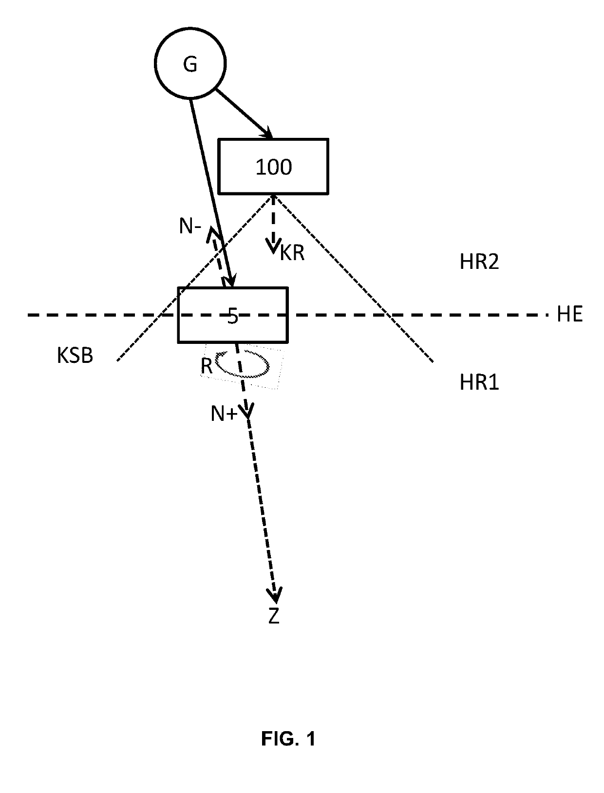
[0014]FIG. 1 shows a schematic representation of a methodology according to embodiments of the system described herein. A gesture generator (G) has a sample card (5) (i.e., “pattern card”) which may have a machine-readable two-dimensional code printed on one side. The pattern card (5) (or more specifically the surface of the pattern card bearing the code) defines a carrier plane (HE). As an alternative to a sample card, an electronic display also may be provided as a carrier medium for the code.

[0015]A camera (100) belonging to an image processing system has a field of view (KSB) which may be essentially determined by the viewing direction or optical axis (KR) of the camera, for example, in a known manner. The viewing direction of the camera (100) may be oriented away from the gesture generator (G). This could be the case, for example, if the gesturer holds the camera (e.g., integrated in a smartphone) with a first hand and the carrier medium (5) of the code with a second hand and p...


PUM


Abstract

A pointing device interacts with a target point arranged on a projection surface of a virtual desktop and a pointing device. A spatial coordinate of a target point may be determined by means of an image processing system from a two-dimensional optical code applied to a carrier plane associated with the pointing device, and may be transmitted as a control variable to a control unit of the projection surface. A spatial position of a normal vector perpendicular to the center of gravity of the surface of the code may be determined. The normal vector may be aligned with the target point by shifting and tilting the carrier plane. A rotational movement of the carrier plane about an axis of rotation perpendicular to the carrier plane may be detected, and an activation signal of the pointing device may be generated as a function of a detected rotational movement.

Description

TECHNICAL FIELD[0001]The system described herein concerns a method of interacting a pointing device with a target point located on a projection screen of a virtual desktop and a pointing device adapted therefor.BACKGROUND OF THE INVENTION[0002]Pointing devices as input devices for the interaction of a user with graphical user interfaces are known in large numbers from the state of the art, whereby their types of execution differ depending on the usage context and technical concept of the user interfaces. Common pointing devices such as a trackball, light pen, graphics tablet, joystick, computer mouse or touch screen or touch pad are primarily designed for user interaction with a real computer screen. For the interaction of a user with a virtual desktop, the so-called Wii® remote controller is known from the state of the art, which is used in connection with computer games or applications on the so-called Wii® platform of the manufacturer Nintendo. In this system, acceleration values...

Claims


Application Information

Patent Timeline
Patent Type & Authority Applications(United States)
IPC IPC(8): G06F3/0346G06F3/038G06F3/01G06F3/03
CPCG06F3/038G06F3/0482G06F3/017G06F3/0304G06F3/0346G06F3/014
Inventor RODE, OLIVER HORST
Owner RODE OLIVER HORST
Why Eureka
Try Eureka