Display device
A display device and display area technology, which is applied in identification devices, nonlinear optics, optics, etc., can solve problems such as hindering the increase of the screen ratio of the display device, and achieve the goal of increasing the screen ratio, improving product quality, and reducing conspicuousness. Effect
- Summary
- Abstract
- Description
- Claims
- Application Information
AI Technical Summary
Problems solved by technology
Method used
Image
Examples
Embodiment 1
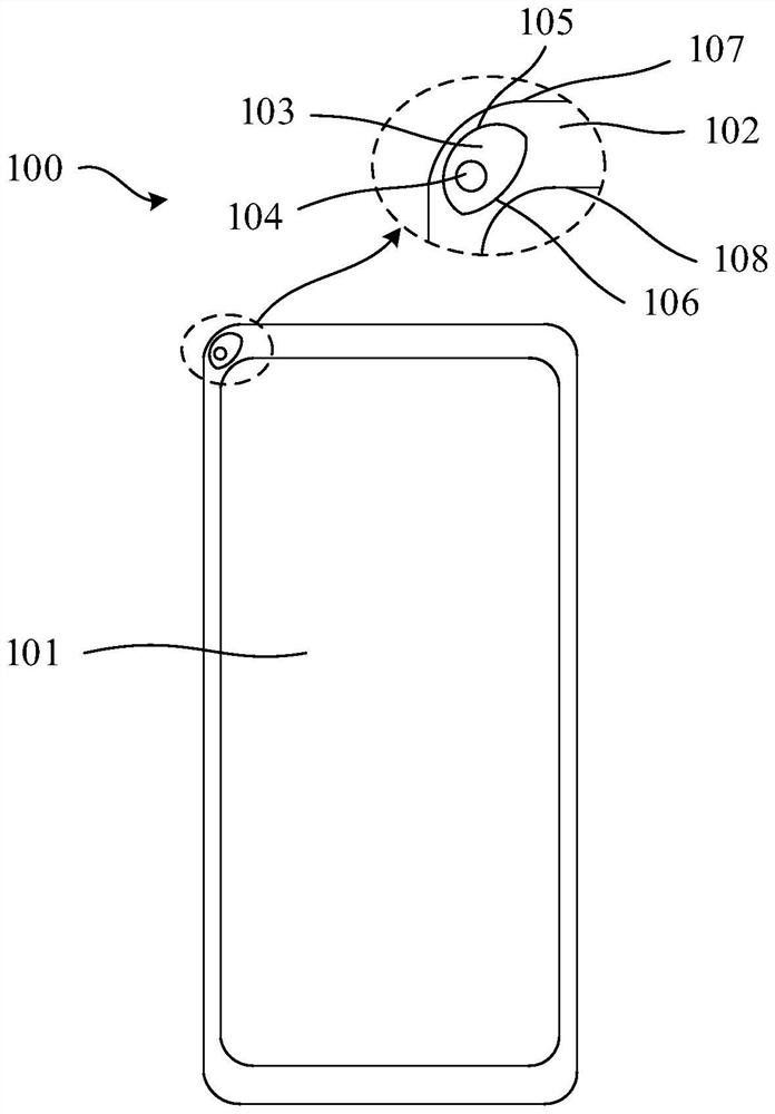
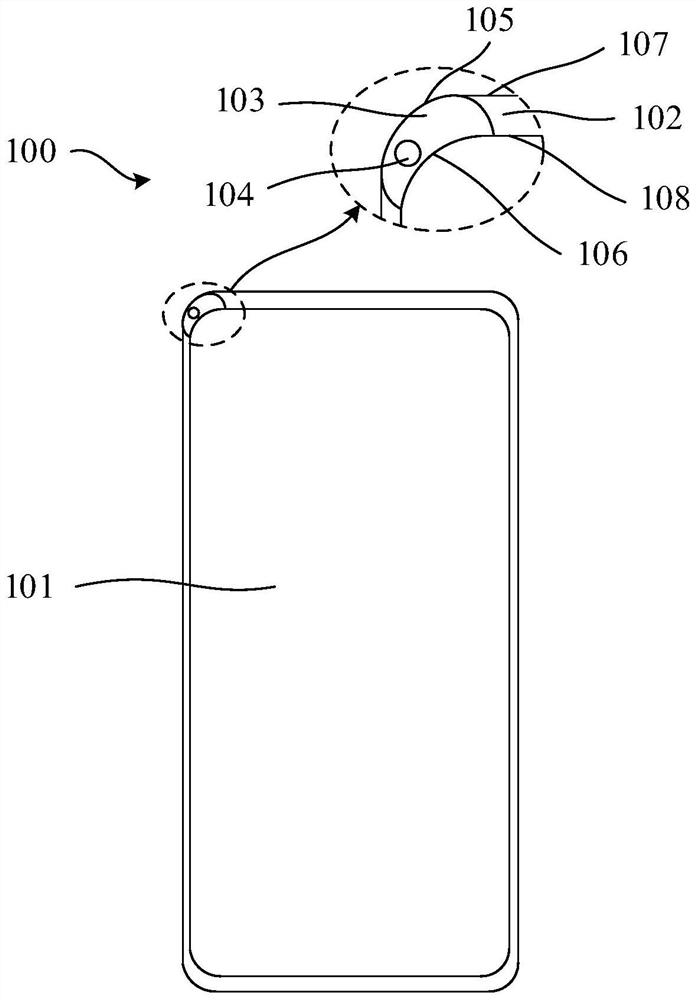
[0064] see figure 1 as well as figure 2 , the middle frame includes four closed first sides 107 , and the display area 101 includes four closed second sides 108 .
[0065] The perforated area 103 is located between the adjacent first side 107 and the adjacent second side 108 .
[0066] In this embodiment, the first arc 105 may have a first overlapping portion with the first side 107 .
[0067] In this embodiment, the second arc 106 may have a second overlapping portion with the second side 108 .
[0068] In this embodiment, the first arc 105 may have a first overlapping portion with the first side 107 , and the second arc 106 may have a second overlapping portion with the second side 108 .
[0069] When the first arc 105 and the first side 107 have a first overlapping portion, the first arc 105 may be adjacent to the first side 107 adjacent to the first arc 105 At the same time, there is an overlapping portion, and the first arc 105 may also have an overlapping portion on...
Embodiment 2
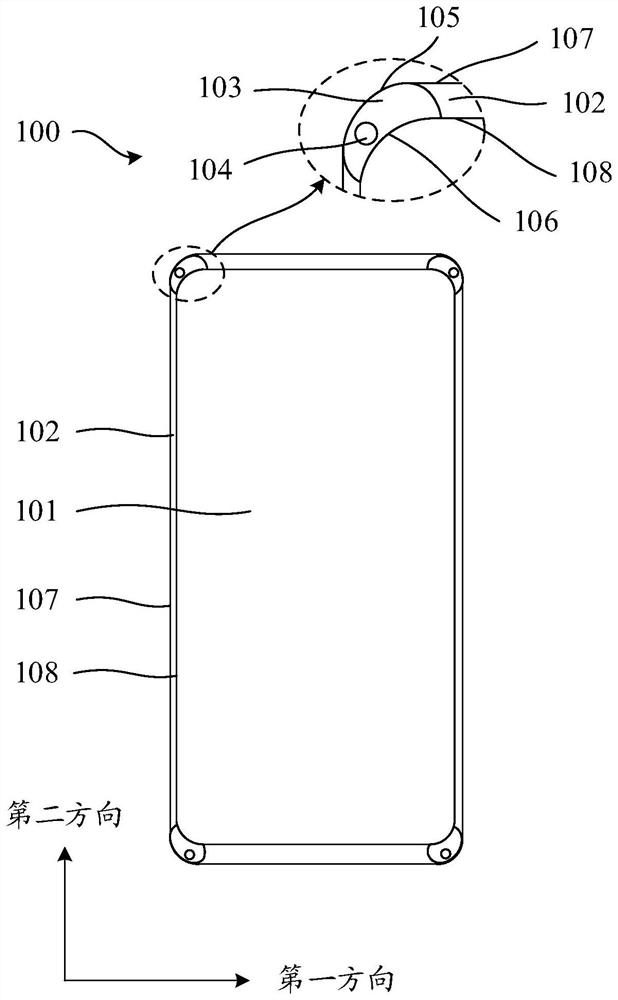
[0084] see image 3 , this embodiment is the same or similar to Embodiment 1, the difference is:
[0085] The display device 100 includes 2N perforated areas 103 , and the perforated areas 103 are arranged symmetrically with respect to a first axis of symmetry along a first direction or a second axis of symmetry along a second direction of the display area 101 .
[0086] Wherein, the first direction is parallel to the extending direction of the scanning lines of the display panel, the second direction is parallel to the extending direction of the data lines of the display panel, and N is a positive integer.
[0087] In this embodiment, when the perforated area 103 is arranged symmetrically with respect to the first axis of symmetry or the second axis of symmetry, the perforated areas located on both sides of the first axis of symmetry or the second axis of symmetry 103 is the same number.
[0088] Since a plurality of the perforated areas 103 are symmetrically arranged in th...
Embodiment 3
[0091] see Figure 4 , this embodiment is the same or similar to the above embodiment, the difference is:
[0092] The display panel further includes a second non-display area 109 surrounding the display area 101 , and the second non-display area 109 is located in the first non-display area 102 .
[0093] In this embodiment, the perforated area 103 is located in an area of the first non-display area 102 except the second non-display area 109 .
[0094]Alternatively, the perforated area 103 has a third overlapping portion with the second non-display area 109 .
[0095] In this embodiment, when the perforated area 103 is located in an area of the first non-display area 102 other than the second non-display area 109, the second non-display area 109 may include a third side .
[0096] The perforated area 103 may be located between the adjacent first side 107 and the adjacent third side.
[0097] The perforated area 103 may have a sixth overlapping portion with the third si...
PUM
 Abstract
Description
Claims
Application Information
 - R&D
- Intellectual Property
- Life Sciences
- Materials
- Tech Scout
- Unparalleled Data Quality
- Higher Quality Content
- 60% Fewer Hallucinations
Browse by: Latest US Patents, China's latest patents, Technical Efficacy Thesaurus, Application Domain, Technology Topic, Popular Technical Reports.
© 2025 PatSnap. All rights reserved.Legal|Privacy policy|Modern Slavery Act Transparency Statement|Sitemap|About US| Contact US: help@patsnap.com


