Bow sight

a sight and bow technology, applied in the field of bow sight, can solve the problem that the bow hunter must frequently cease bow hunting, and achieve the effect of improving the sighting of the targ

Inactive Publication Date: 2008-05-20
TUPPER JR JOHN M
View PDF16 Cites 12 Cited by
  • Summary
  • Abstract
  • Description
  • Claims
  • Application Information

AI Technical Summary

Benefits of technology

[0005]The present invention is generally directed to a bow sight which enhances sighting of a target in a dim environment. The bow sight includes a generally transparent bow sight body. At least one fiber optic cable is provided in the bow sight body and generally surrounds a line of sight through the bow sight body.

Problems solved by technology

Therefore, as dusk approaches, a bow hunter must frequently cease bow hunting due to inadequate lighting.

Method used


Image

  • Bow sight
  • Bow sight
  • Bow sight

Examples


Embodiment Construction

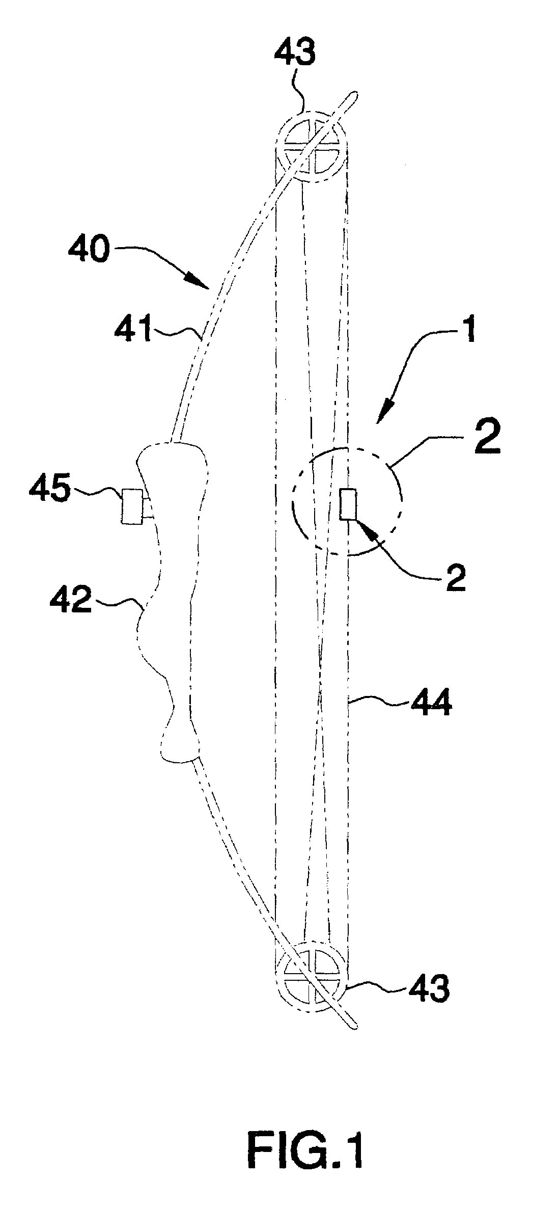
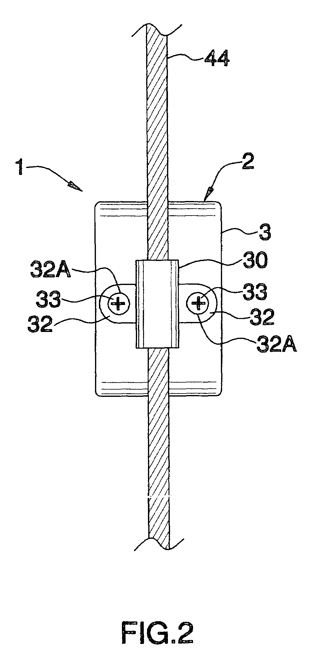
[0011]Referring to the drawings, an illustrative embodiment of the bow sight according to the present invention is generally indicated by reference numeral 1. As shown in FIG. 1, the bow sight 1 is typically mounted on a bow 40 which may include an elongated, flexible, arcuate bow body 41 fitted with a hand grip 42. A front bow sight 45, which typically includes a sight pin (not shown), is mounted typically on the bow body 41 or hand grip 42. Rotatable string tensioning wheels 43 are mounted on respective ends of the bow body 41. A bow string 44 is trained on the string tensioning wheels 43. The bow sight 1 is typically mounted as a rear bow sight on the bow string 44 and enhances sighting of the sighting pin (not shown) in the front bow sight 45, particularly under low-light conditions, as will be hereinafter described.

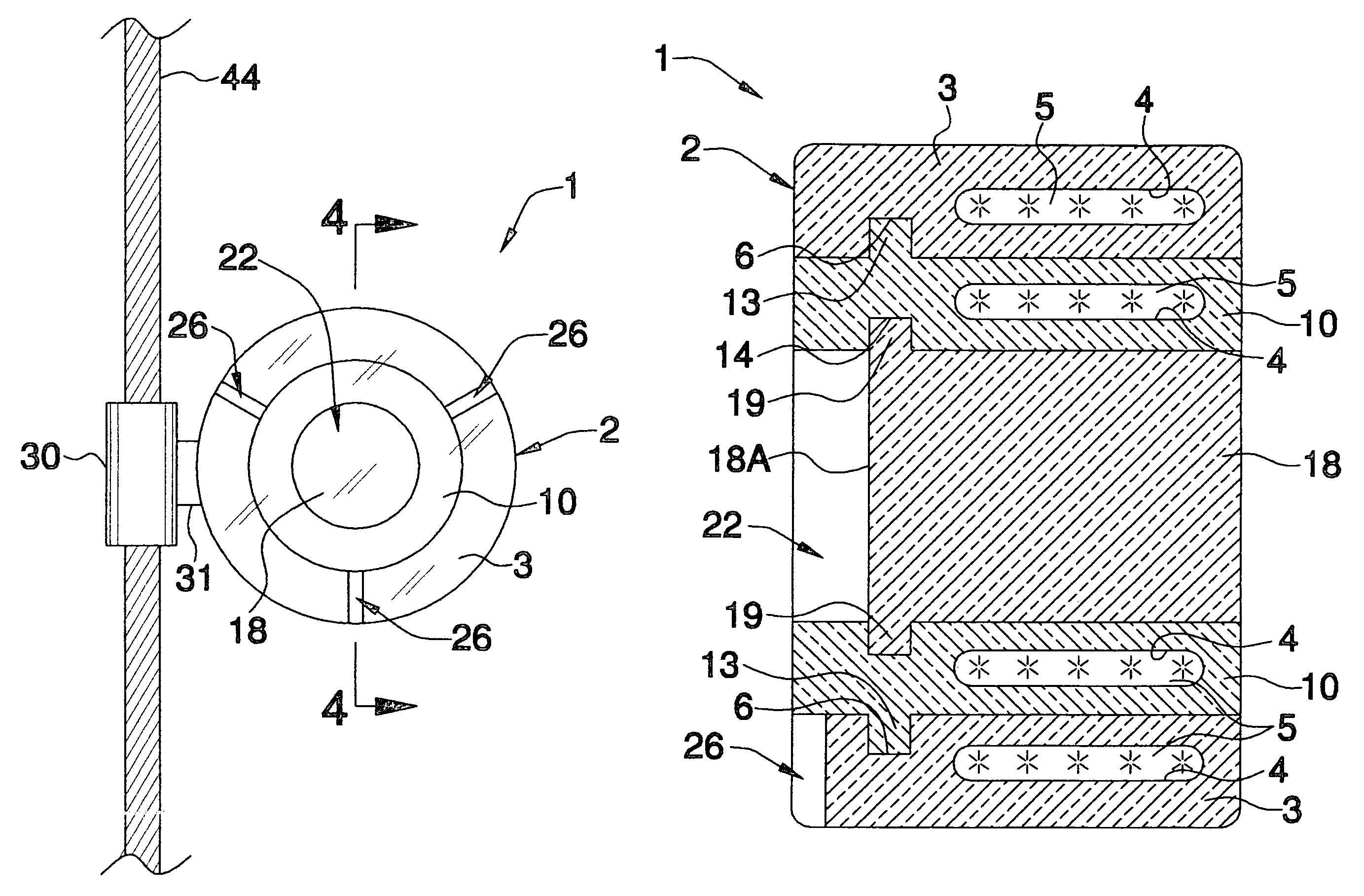
[0012]As shown in FIGS. 3 and 4, the bow sight 1 includes a bow sight body 2 which may have a generally cylindrical or disc-shaped configuration, as shown. The bow s...


PUM


Abstract

A bow sight is disclosed. The bow sight includes a generally transparent bow sight body. At least one fiber optic cable is provided in the bow sight body and generally surrounds a line of sight through the bow sight body.

Description

[0001]The present invention relates to bow sights for bows. More particularly, the present invention relates to a rear bow sight which enhances sighting of a sight pin in a front bow sight of a bow, particularly under low-light conditions.BACKGROUND OF THE INVENTION[0002]Bow hunting has gained increasing popularity in the United States and abroad. Bow hunting is suitable for hunting a variety of wild game including deer, elk and bear, for example. Many bow hunters are challenged by the visual acuity and hand-to-eye coordination which is necessary to properly sight an arrow to a target for a successful kill.[0003]Typically, a bow includes a front bow sight which is mounted on the body or frame of the bow and includes a sight pin. A rear bow sight is mounted typically on the string of the bow and includes a transparent peep which may be provided with cross-hairs. Adequate lighting is necessary for a hunter to aim an arrow at a target, as this requires alignment of the sight pin in the...

Claims


Application Information

Patent Timeline
Patent Type & Authority Patents(United States)
IPC IPC(8): F41G1/467
CPCF41G1/467
Inventor TUPPER, JR., JOHN M.
Owner TUPPER JR JOHN M
Why Eureka
Try Eureka