Three-side stacker

a stacker and three-side technology, applied in the field of three-side stackers, can solve problems such as troublesome errors and moving tubes, and achieve the effects of reducing installation space, improving sight on fork arms, and simple measuremen

Active Publication Date: 2010-09-14
JUNGHEINRICH AG
View PDF19 Cites 2 Cited by
  • Summary
  • Abstract
  • Description
  • Claims
  • Application Information

AI Technical Summary

Benefits of technology

[0010]In the drive equipment according to the invention for the load supporting means or the lifting scaffold of a three-side stacker, respectively, it is advantageous when the respective turning position can be determined. As a consequence, one embodiment of the present invention provides that a transmitter is connected with the spindle, and an angle sensor is arranged in the casing. Different mechanical or contactless arrangements of sensor and transmitter are conceivable. According to a further embodiment of the present invention, a particularly simple measure is that a gearwheel sits on the spindle, which meshes with a sprocket of a potentiometer.
[0011]Several advantages are attained by the present invention. The installation frame for the pivoting drive is extremely small and permits to place the side push frame further downward, through which the visible edge is moved towards the downside and thus it improves the sight on the fork arms. Even in the horizontal direction, a reduction of the installation space is possible. The assembly and the maintenance are improved with respect to conventional drives, not at least by the reduction of the number of the individual parts. A very important advantage is that the force which is exerted by the mast or the load supporting means is directly taken up by the spindle. Through this, the rotational drive is not only a driving means but also a force receiving means.

Problems solved by technology

As is known, movable tubes are a source of troubles and errors, in particular when the actuated part performs a turning or swivelling movement, respectively.

Method used


Image

  • Three-side stacker
  • Three-side stacker
  • Three-side stacker

Examples


Embodiment Construction

[0020]While this invention may be embodied in many different forms, there are described in detail herein a specific preferred embodiment of the invention. This description is an exemplification of the principles of the invention and is not intended to limit the invention to the particular embodiment illustrated

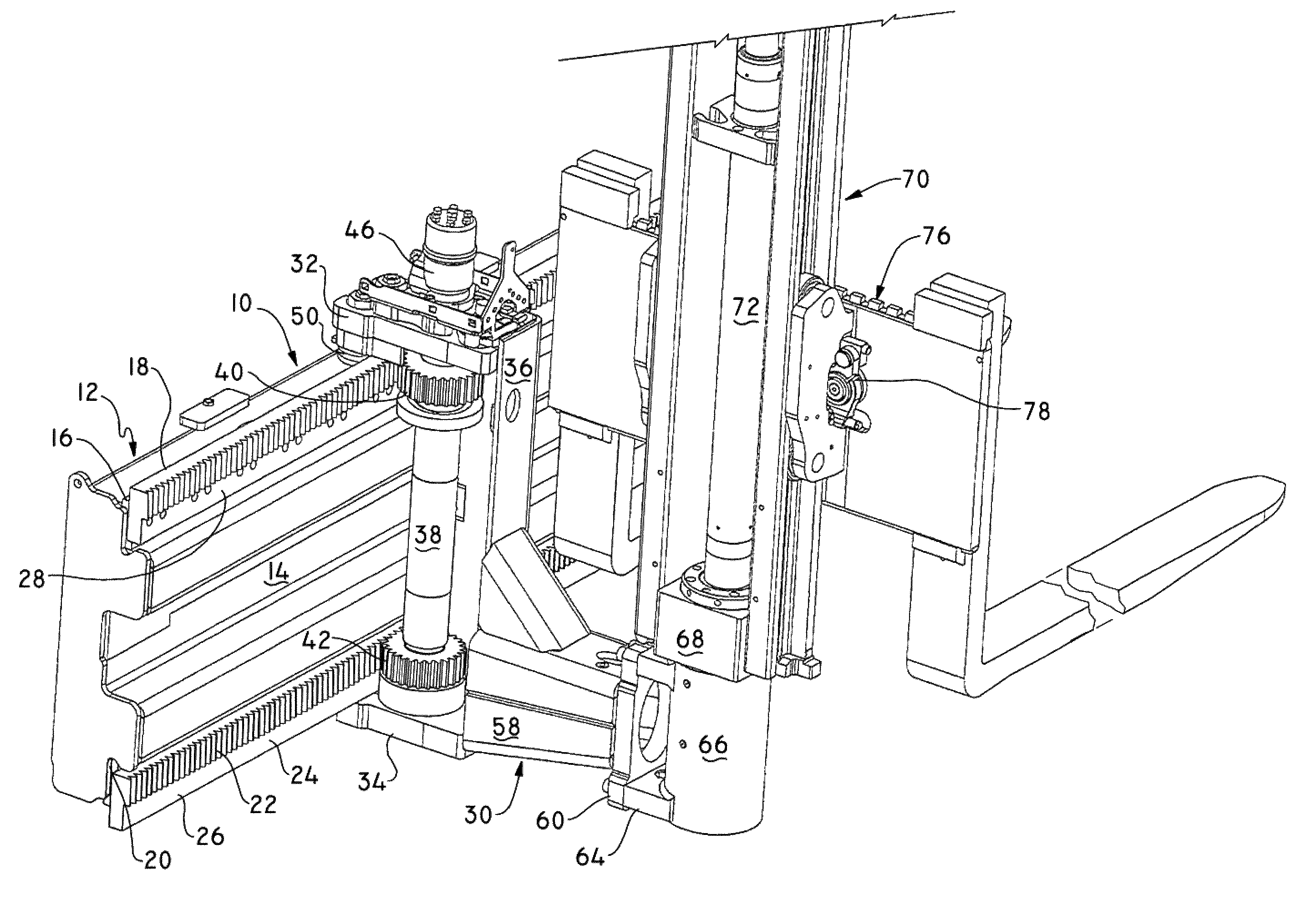
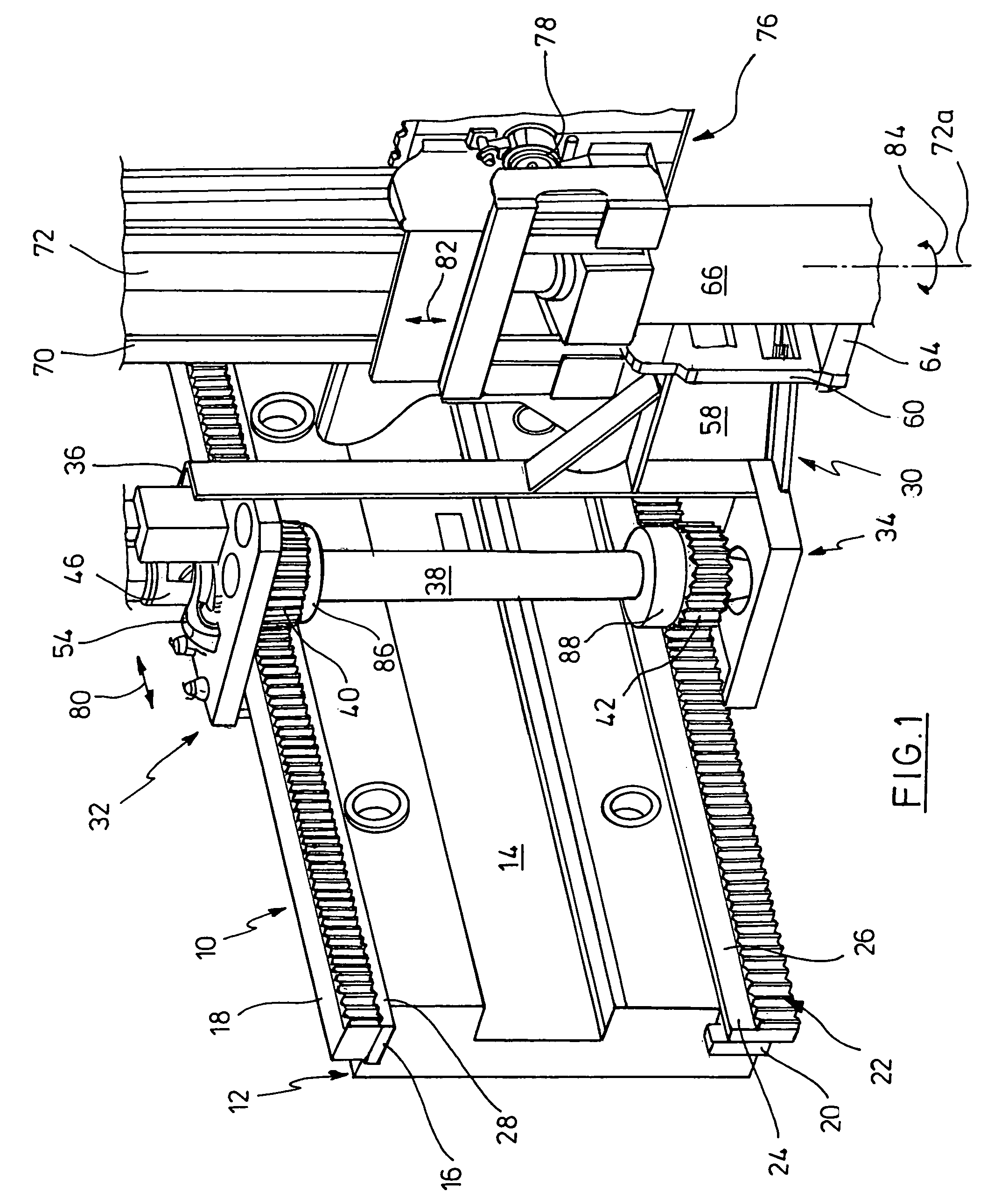
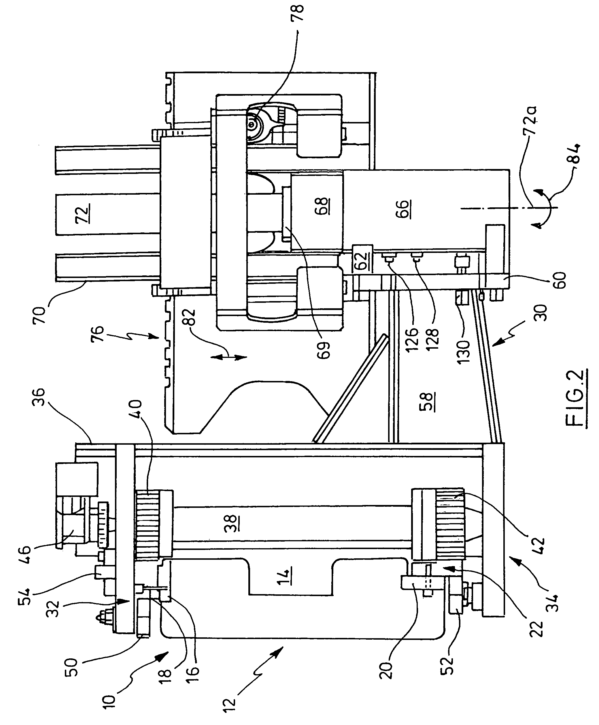
[0021]In the FIGS. 1 and 2, a side push frame 10 of a three-side stacker is designated with 10. The three-side stacker is not shown for the rest. Insofar, reference is made to U.S. Pat. No. 4,470,750, for instance. The side push frame 10 is fixed horizontally on the front side of the three-side stacker, for instance on the vehicle itself or on a lifting mast or even on a cab, which is height-movably guided on the lifting mast.

[0022]The side push frame has a frame profile 12, U-shaped in its cross section, through which a channel 14 is formed. On the upper side of the frame profile 12, a flat rail 16 is fixed. A toothed rack 18 is fixed on the rail 16. Rail 16 and toothed rack ...


PUM


Abstract

A three-side stacker with a side push frame at one end of the stacker, on which a side arm is horizontally traversable mounted, wherein the side arm has a first traversable portion mounted on the side push frame and a second portion, which is mounted pivotally around a vertical axis on the first portion and on which a load supporting means is mounted, which is actuable by a hydraulic lifting cylinder, and a pivoting equipment for the second portion, mounted on the first portion, wherein the casing of a hydraulic rotational drive with a rotatable spindle is fixed on the first portion, wherein a portion of the spindle is splinedly connected with a holder or a lifting scaffold for the load supporting means outside the casing.

Description

CROSS-REFERENCE TO RELATED APPLICATIONS[0001]Not applicable.STATEMENT REGARDING FEDERALLY SPONSORED RESEARCH[0002]Not applicable.BACKGROUND OF THE INVENTION[0003]Such a three-side stacker has become known from U.S. Pat. No. 4,470,750, the entire contents of which are hereby incorporated by reference in its entirety, for instance. For instance, it is used as a storage rack conveyor. A side push or guide frame is arranged on the front end, transversely to the longitudinal axis of the apparatus. Depending on the type, the side push frame is connected stationarily with the vehicle or guided in the height on a lifting mast or so. Finally, it is also possible to fix the side push frame on the front side of the cab of the vehicle, which is itself as a whole traversable in the height on the lifting mast. In this case, the three-side stacker represents an order picking apparatus. A side arm is horizontally traversable on the side push frame. The side arm consists of two portions, namely a fi...

Claims


Application Information

Patent Timeline
Patent Type & Authority Patents(United States)
IPC IPC(8): B66F9/14
CPCB66F9/147
Inventor SCHONAUER, MICHAEL
Owner JUNGHEINRICH AG
Why Eureka
Try Eureka