

System and method for distributed power control in a communications system
a communication system and distributed power technology, applied in the field of digital communications, can solve the problems of significantly reducing the system performance, inter-link interference may have a significant impact on the overall performance of the communications system, etc., and achieve the effect of simplifying the measurement of channels, simplifying the computation of transmit power levels, and simplifying the coordination and signaling between bss, rns and mss
Inactive Publication Date: 2014-04-22
FUTUREWEI TECH INC
View PDF9 Cites 205 Cited by
- Summary
- Abstract
- Description
- Claims
- Application Information
AI Technical Summary
Benefits of technology
The patent text describes a system for controlling power in a wireless communication network. The use of a power pattern for the transmission of specific devices helps to simplify the measurement of channels and the coordination of transmissions between multiple devices. This system is also efficient and reduces the impact on the overall communication system. Overall, this system simplifies power control and improves the overall performance of wireless networks.
Problems solved by technology
Typically, in a multi-user communications system, inter-link interference may have a significant impact on overall performance of the communications system.
For example, inter-link interference may significantly reduce the system performance, such as a sum of the data rates of links simultaneously utilizing the same radio frequency resource.
However, they tend to be optimized for single-hop power control algorithms and do not typically apply to communications systems with relay nodes since such systems are multi-hop systems.
Method used
View moreImage
Smart ImageViewing Examples

Examples
case 1
[0085] λ1=ζ3=1 and λ2=λ1=0
case 2
[0086] λ1=λ3=0 and λ2=λ4=1
case 3
[0087] λ1 and λ2ε(0, 1) and λ4ε(0, 1]
Login to View More PUM
 Abstract
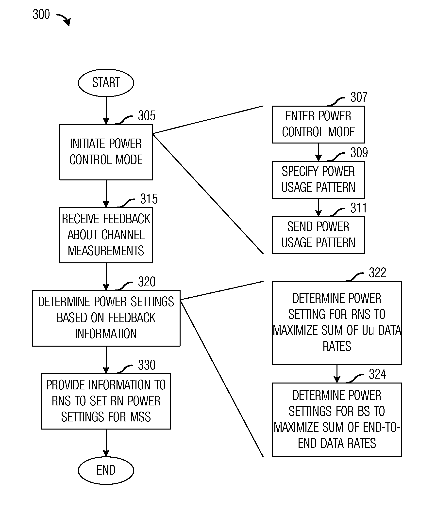
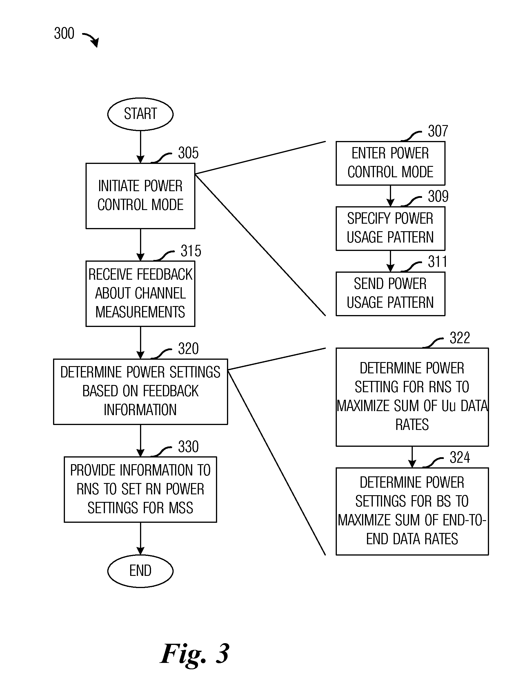
An embodiment method for power control in a multi-hop communications system includes transmitting a power usage pattern for each relay node in a subset of relay nodes served by a communications controller, where the power usage pattern specifies transmit power levels for the relay node while the relay node is operating in a power control mode. The method also includes receiving channel measurements of access links between the relay nodes in the subset of relay nodes and subscriber equipment served by the relay nodes, determining backhaul link transmit power levels and access link transmit power levels based on the channel measurements of access links and channel measurements of backhaul links between the communications controller and the relay nodes, and transmitting the access link power levels to the subset of relay nodes.
Description
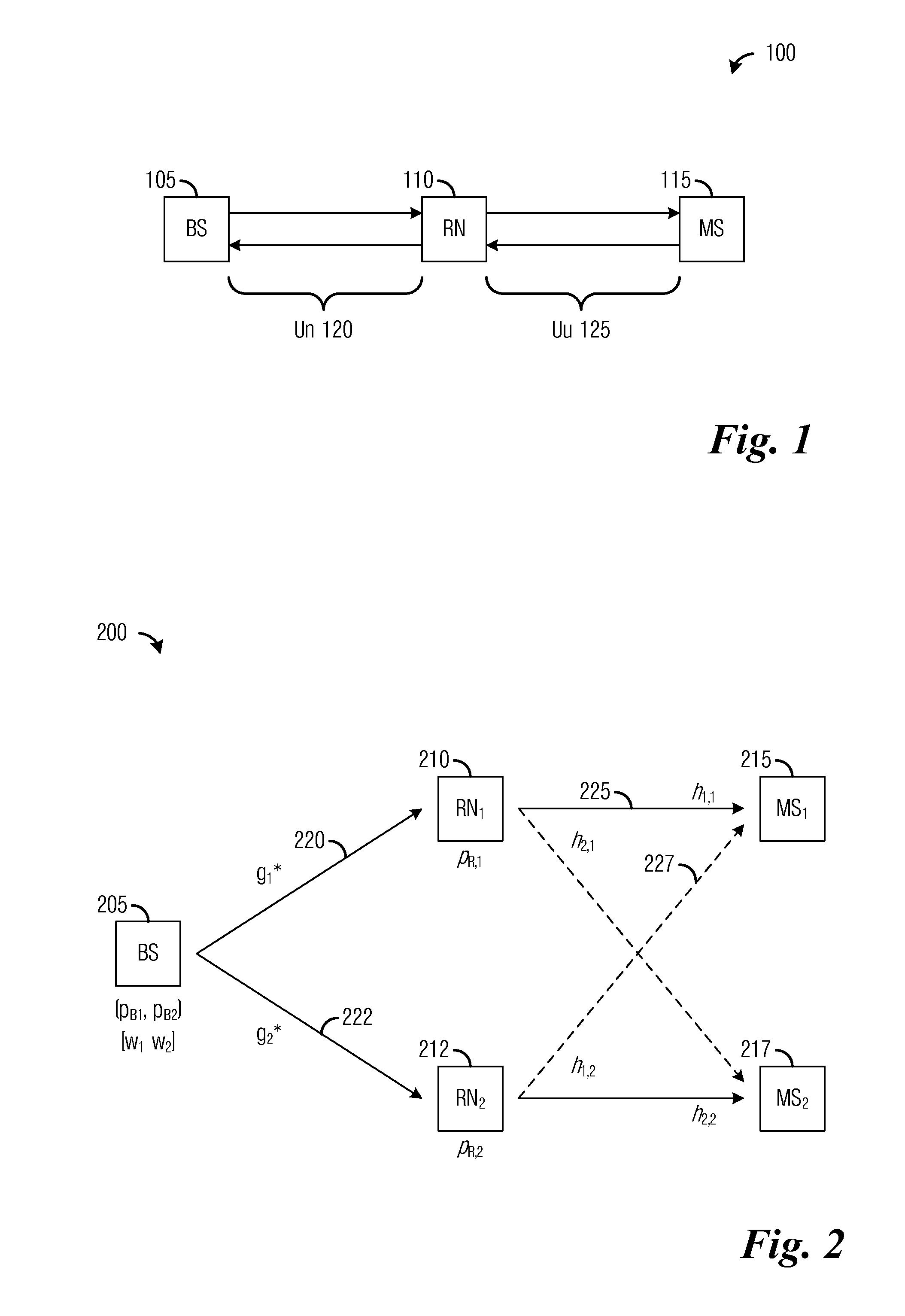
[0001]This application claims the benefit of U.S. Provisional Application No. 61 / 388,330, filed on Sep. 30, 2010, entitled “Method for Power Control at the Base Station and at the Relay Nodes in a Wireless Relay Network,” which application is hereby incorporated herein by reference.TECHNICAL FIELD[0002]The present invention relates generally to digital communications, and more particularly to a system and method for distributed power control in a communications system.BACKGROUND[0003]In upcoming wireless communications systems, such as The Third Generation Partnership Project (3GPP) Long Term Evolution-Advanced (LTE-Advanced), relay nodes and relay communications are being considered as an effective solution in providing extended coverage and / or improved data rate. For example, in a downlink of a relay-based communications system, a base station (BS) (also commonly referred to as a controller, communications controller, NodeB, enhanced NodeB (eNB), and so on) may transmit to a relay...
Claims
Login to View More Application Information
Patent Timeline
 Patent Type & AuthorityPatents(United States)
IPC IPC(8): H04B1/60
CPCH04W88/04H04W24/10H04W52/46
InventorTRUONG, KIEN TRUNGKWON, YOUNG HOONSARTORI, PHILIPPEAL-SHALASH, MAZIN
OwnerFUTUREWEI TECH INC