
Parameter state estimation

a parameter state and parameter technology, applied in the direction of brake systems, instruments, etc., can solve the problems of reducing the service life of one or more driveline components, affecting the operation of powertrain systems, and unnoticeable to operators, so as to facilitate the implementation of torque oscillation damping control and reduce the service life. the effect of high level of signal nois

Inactive Publication Date: 2007-09-27
GM GLOBAL TECH OPERATIONS LLC
View PDF5 Cites 198 Cited by
  • Summary
  • Abstract
  • Description
  • Claims
  • Application Information

AI Technical Summary

Benefits of technology

The invention is a method and control system for estimating and controlling the state of a powertrain system with multiple torque-generative devices. The system is modeled as a system of multiple mass-spring devices with multiple degrees of freedom and torque control devices. The invention uses a state estimator to estimate the states of each component in the system, including speed and torque. The system is controlled based on the estimated states and a matrix of feedback gains. The invention allows for real-time damping control and accommodates changes in vehicle parameters, transmission losses, and engine torque output errors. The technical effects of the invention include improved control accuracy, reduced overshoot, and improved stability and efficiency of the powertrain system.

Problems solved by technology

Engineers implementing powertrain systems encounter driveline vibrations, which typically range from unnoticeable to objectionable to an operator.
Driveline vibrations are customer dissatisfiers, and may reduce service life of one or more driveline components.
Such torque cancellation systems typically pass driveline inputs through signal conditioning filters, which slow system responsiveness.
Slow system response often leads to a bump or overshoot that occurs when there is an aggressive operator torque request, due to delays in transient responses required to develop filters.
However, single feedback / single control vibration control systems do not provide adequate damping in a system having multiple devices operable to generate vibrations in a driveline.
However, some operating states may be difficult to sense directly, due to a lack of ability to directly sense certain operating states, e.g. torque, and added cost and complexity required to implement such sensing systems.

Method used


Image

  • Parameter state estimation
  • Parameter state estimation
  • Parameter state estimation

Examples


Embodiment Construction

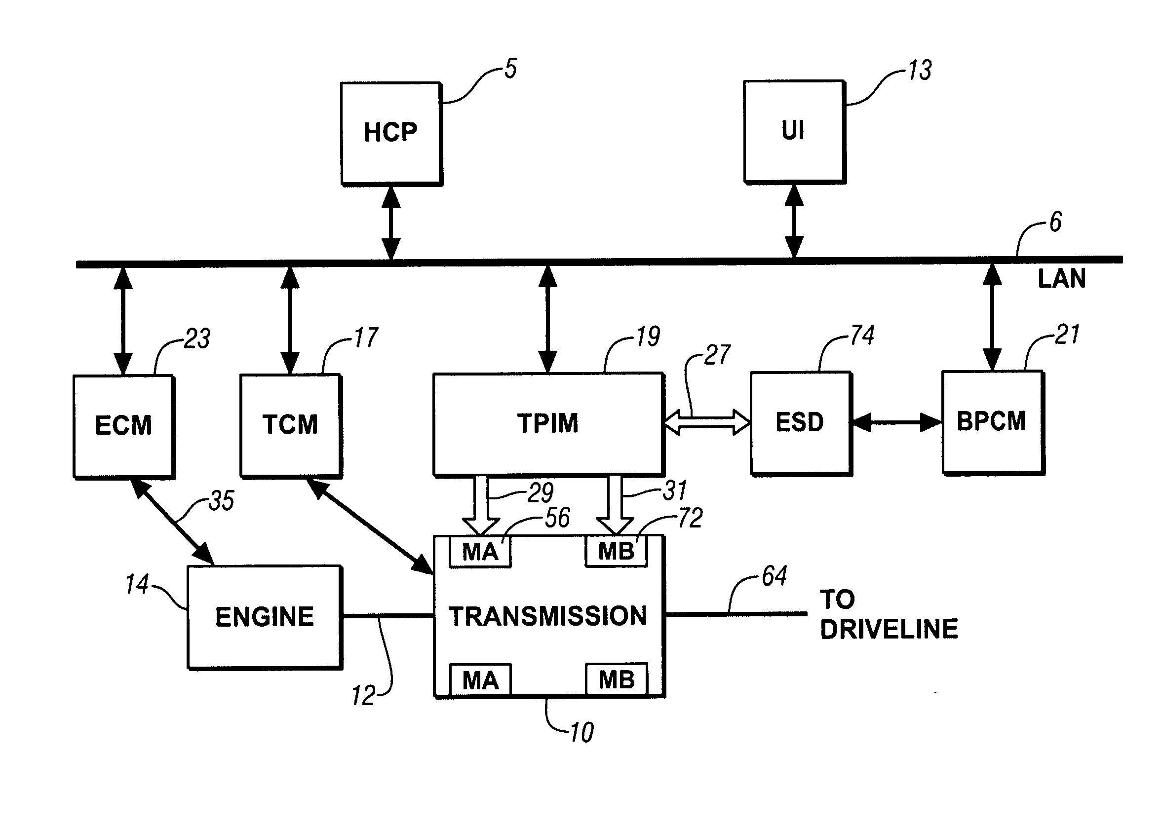
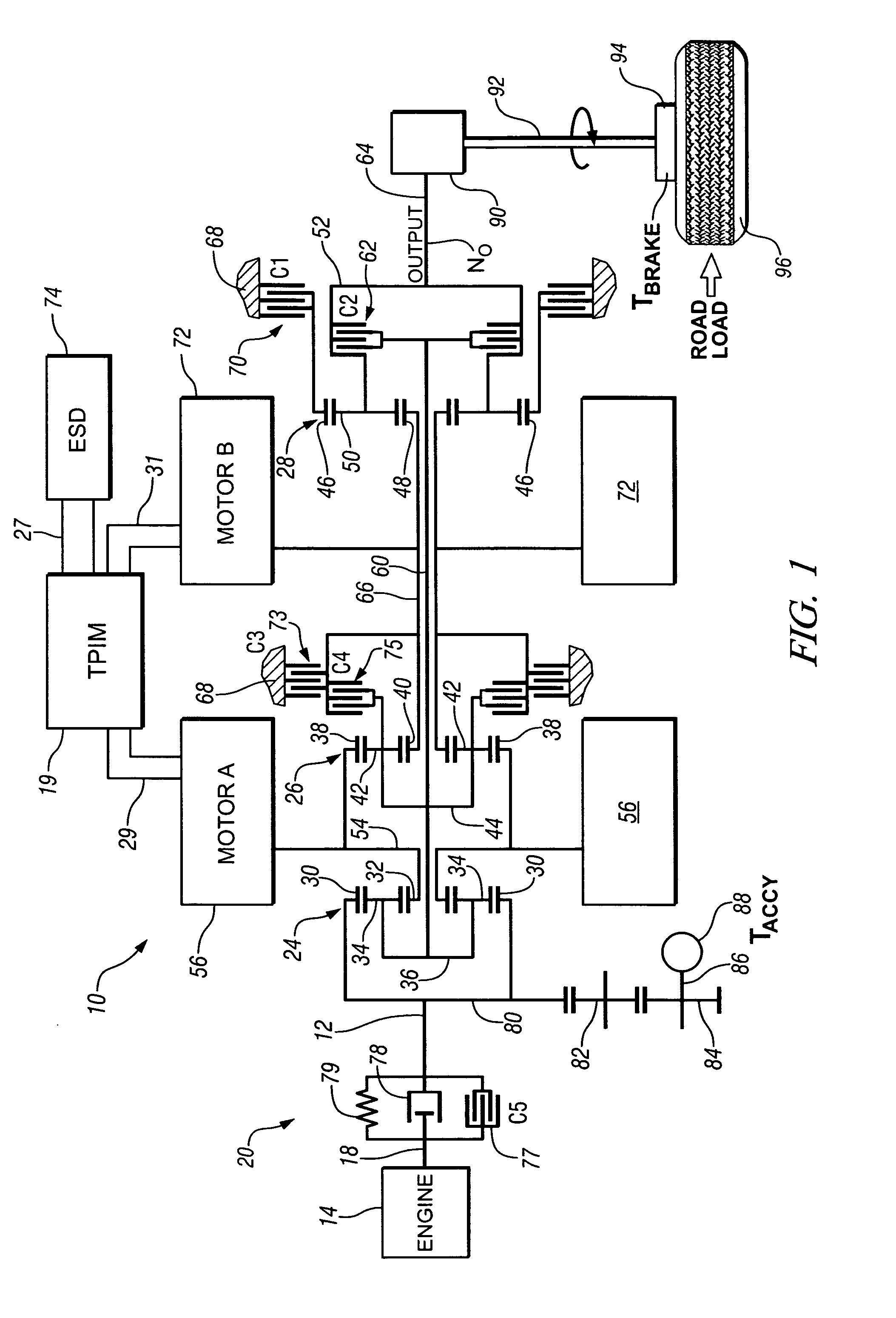
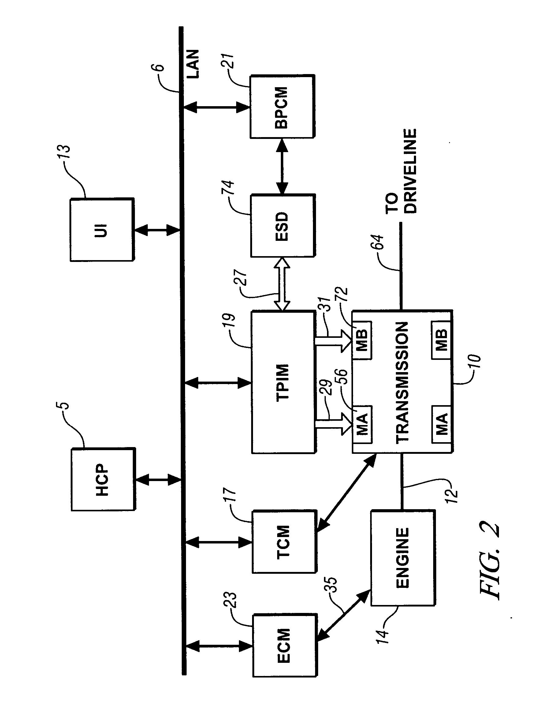
[0025] Referring now to the drawings, wherein the showings are for the purpose of illustrating the invention only and not for the purpose of limiting the same, FIGS. 1 and 2 show a system comprising an engine 14, transmission 10, control system, and driveline which has been constructed in accordance with an embodiment of the present invention.

[0026] Mechanical aspects of exemplary transmission 10 are disclosed in detail in commonly assigned U.S. Patent Application Publication No. U.S. 2005 / 0137042 A1, published Jun. 23, 2005, entitled Two-Mode, Compound-Split, Hybrid Electro-Mechanical Transmission having Four Fixed Ratios, which is incorporated herein by reference. The exemplary two-mode, compound-split, electromechanical hybrid transmission embodying the concepts of the present invention is depicted in FIG. 1, and is designated generally by the numeral 10. The hybrid transmission 10 has an input member 12 that may be in the nature of a shaft which may be directly driven by an eng...


PUM


Abstract

The state estimator provides parametric estimates for operating states not readily measurable with production powertrain and driveline hardware, such as real-time torque values of axles and dampers. This facilitates implementation of torque oscillation damping control schemes which use multivariable feedback. A control parameter is estimated for a powertrain system having multiple torque-generative devices operably connected to a transmission device having a torque output to a driveline. This includes establishing a plurality of equations operable to estimate the control parameter and other operating parameters based upon torque inputs. The operating parameters comprise operating speeds of the powertrain system and driveline. The operating parameters that comprise operating speeds of the powertrain system and driveline are determined. Coefficients of the plurality of equations are adjusted based upon the operating speeds of the powertrain system.

Description

TECHNICAL FIELD [0001] This invention pertains generally to hybrid powertrain control systems, and more specifically to estimating parameter states for use in damping powertrain and driveline vibrations. BACKGROUND OF THE INVENTION [0002] Various hybrid powertrain architectures are known for managing the input and output torques of various prime-movers in hybrid vehicles, most commonly internal combustion engines and electric machines. One such hybrid powertrain architecture comprises a two-mode, compound-split, electromechanical transmission which utilizes an input member for receiving power from a prime mover power source and an output member for delivering power from the transmission. First and second motor / generators are operatively connected to an energy storage device for interchanging electrical power between the storage device and the first and second motor / generators. A control unit is provided for regulating the electrical power interchange between the energy storage devic...

Claims


Application Information

Patent Timeline
Patent Type & Authority Applications(United States)
IPC IPC(8): G06F17/00
CPCB60K1/02B60K6/365B60K6/445B60W20/00B60W2550/12F16H2057/0012F16H2037/102F16H2037/104F16H2037/106Y02T10/6239F16H61/061B60W2555/20Y02T10/62B60W10/10B60W10/06B60W10/08B60W20/40
Inventor MORRIS, ROBERT L.
Owner GM GLOBAL TECH OPERATIONS LLC
Learn More