However, some of these techniques do not rely on fundamental physical effects, and thus could be more effective in some cases and less effective in others.
(1) A. Roger and D. Maystre, J. Opt. Soc. Am, 70 (12), pp. 1483-1495 (1979) and A. Roger and D. Maystre, Optica Acta, 26 (4), pp. 447-460 (1979) describe and systematically analyze the problem of reconstruction of the line profile of a
grating from its
diffraction properties (the inverse scattering problem). A later article "
Grating Profile Reconstruction by an Inverse Scattering Method", A. Roger and M. Breidne,
Optics Comm., 35 (3), pp. 299-302 (1980) discloses how the idea disclosed in the above articles can be experimentally used. The experimental results show that the line profile can be fitted such that the calculated
diffraction efficiency will closely match the
diffraction efficiency measured as a function of
wavelength for "-1"
diffraction order. The comparison of these experimental results with
electron microscopy measurement showed a reasonable agreement.
(2) "Reconstruction of the Profile of Gold Wire Gratings: A comparison of Different Methods", H. Lochbihler et. al., Optik, 98 (1), pp. 21-25 (1994) deals with the comparison of the results of several experimental techniques. Both
optical transmittance and reflectance efficiencies were measured in the "0" order as a function of
wavelength. By fitting the measurements to theoretical spectra calculated using diffraction theory, the
grating profile was found. Comparison of these results with the results of X-
ray diffraction efficiency and
electron microscopy showed a good agreement.
(3) Voskovtsova, L. M. et al. , Soviet Journal of Optical Technology 60 (9) pp.617.varies.19 (1993) studies the properties of gratings fabricated by replica technique. It has been found that the line profile of the hologram
diffraction grating differs from the calculated sinusoidal profile. This difference leads to a difference in the spectral
diffraction efficiency, an effect that was utilized for
process control.
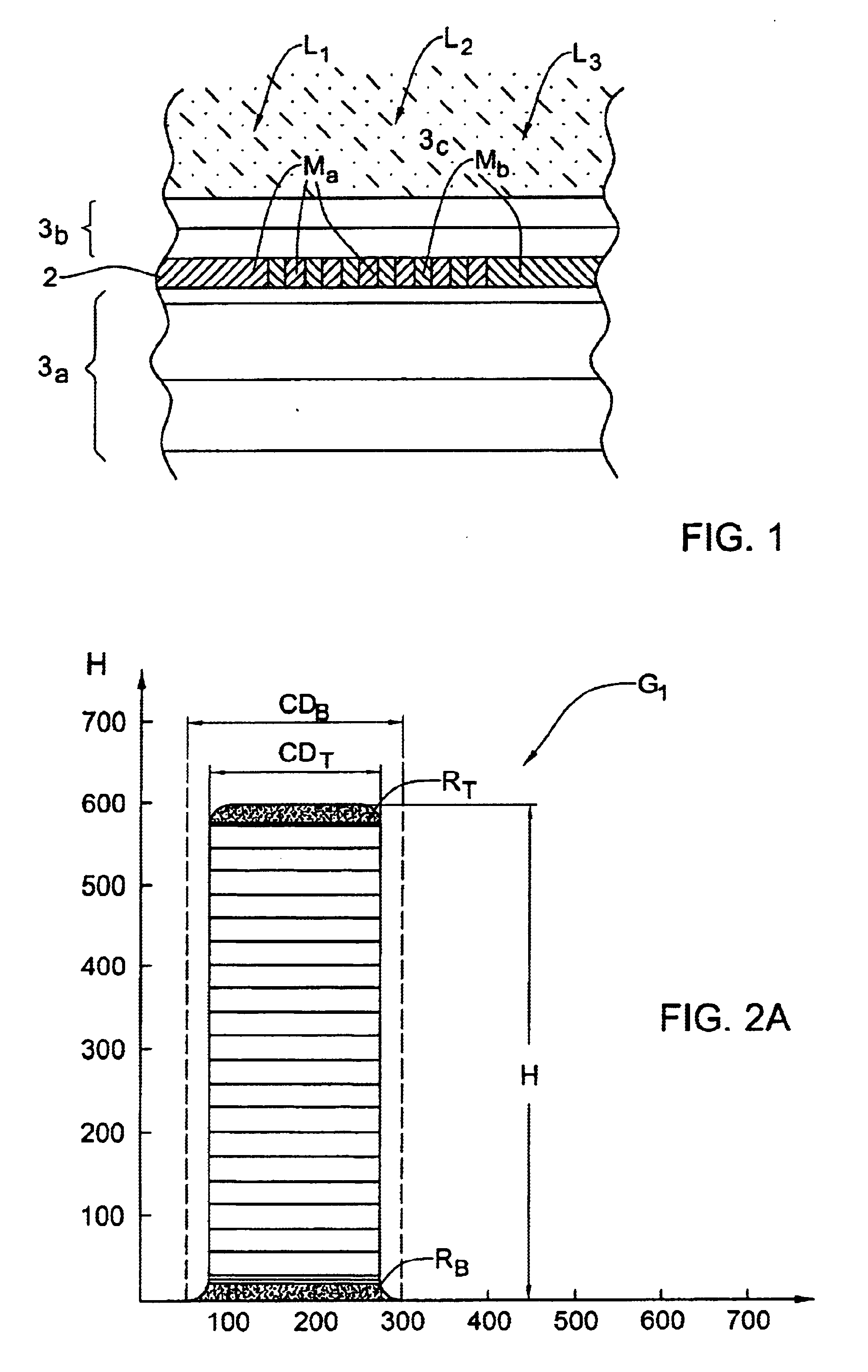
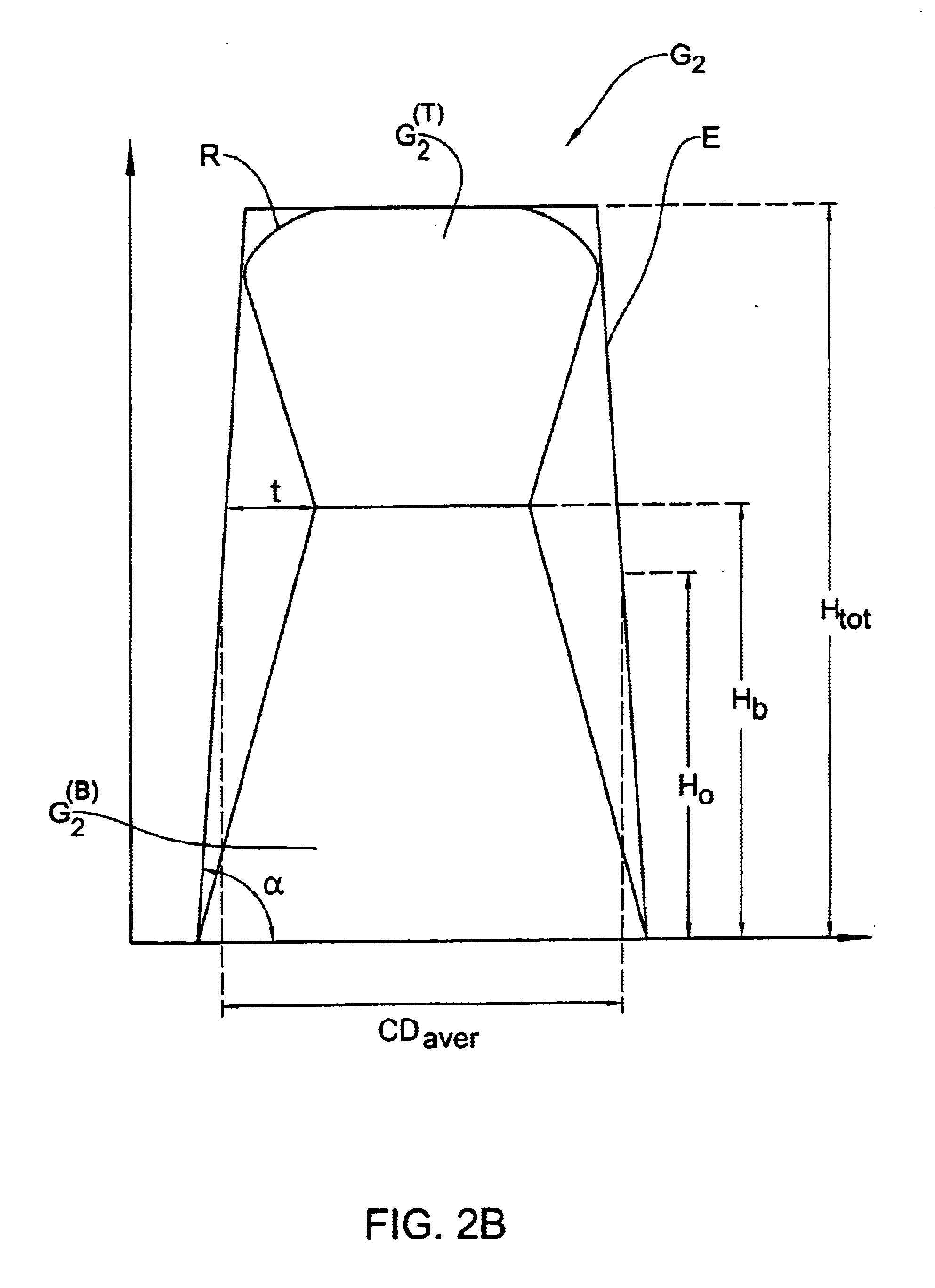
(4) Savitskii, G. M. and Golubenko, I. V.,
Optics and
Spectroscopy 59 (2), pp.2514 (1985) describes a theory for the reflection properties of diffraction gratings with a groove profile which is a trapezoid with rounded comers. Such gratings can be fabricated by a holographic technique with photosensitive materials. It was found that the parameters of the trapezoidal profile, such as the depth of the groove, the width of a flat top and the slope of the side walls, affect the
diffraction efficiency of the
grating working in the auto collimation regime for the "-1" order.
(5) Spikhal'skii A. A., Opt Commun 57 (6) pp. 375-379 (1986) presents the analysis of the spectral characteristics of gratings etched into a
dielectric material. It has been found that these characteristics can be significantly varied by slightly changing the grating groove profile.
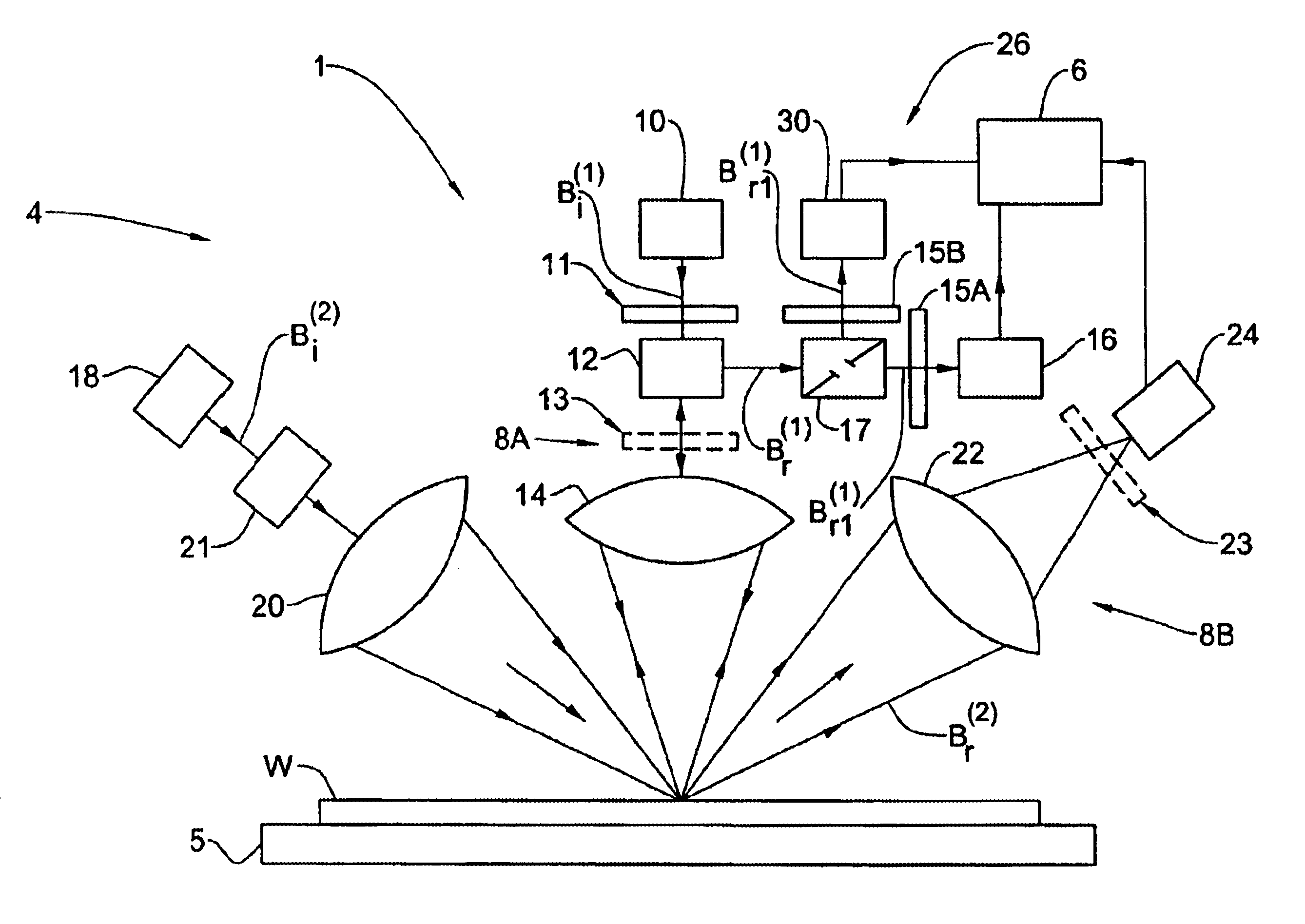
(6) U.S. Pat. No. 5,867,276 discloses a technique for
broadband scatterometry, consisting of the illumination of a sample with an incident
light beam having a broad
spectral composition and detecting a beam of light diffracted from the sample with a
spectrometer. The technique is aimed at obtaining the spectrally-resolved diffraction characteristics of the sample for determining the parameters of the sample. The patent suffers from the following drawbacks: the measurements are done in the "0"
diffraction order which is insensitive to asymmetries in the profile; and the analysis is done using the Neural Network is (N.N.) method, which is sub-optimal by nature for applications requiring a
high resolution. Additionally, the method does not take into account the need to focus the light onto a small spot, which is determined by the small area of the
test structure allowed in the scribe line.
(C) U.S. Pat. Nos. 4,710,642 and 5,164,790 disclose optical instruments which require to rotate the sample under test, which is definitely a
disadvantage.
The main disadvantages of such a technique are as follows: it requires the use of
moving parts, the calibration of an angle in a dynamical situation, and has a
limited angle range which does not provide enough information allowing accurate extraction of profile.
Any suitable component for destroying the coherence always reduces the
system resolution, thereby reducing the amount of obtained information.

