
Contactless intuitive seat adjuster control

a technology of seat adjuster and control, which is applied in the direction of dynamo-electric converter control, motor/generator/converter stopper, pulse technique, etc., can solve the problems of unintended sensor actuation, sensor activation, and electrical charge generation of the piezoelectric elemen

Inactive Publication Date: 2008-06-24
LEAR CORP
View PDF31 Cites 18 Cited by
  • Summary
  • Abstract
  • Description
  • Claims
  • Application Information

AI Technical Summary

Benefits of technology

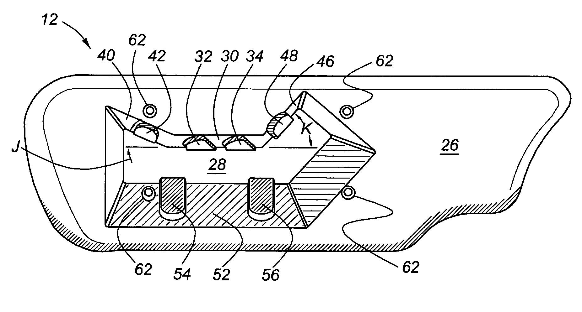
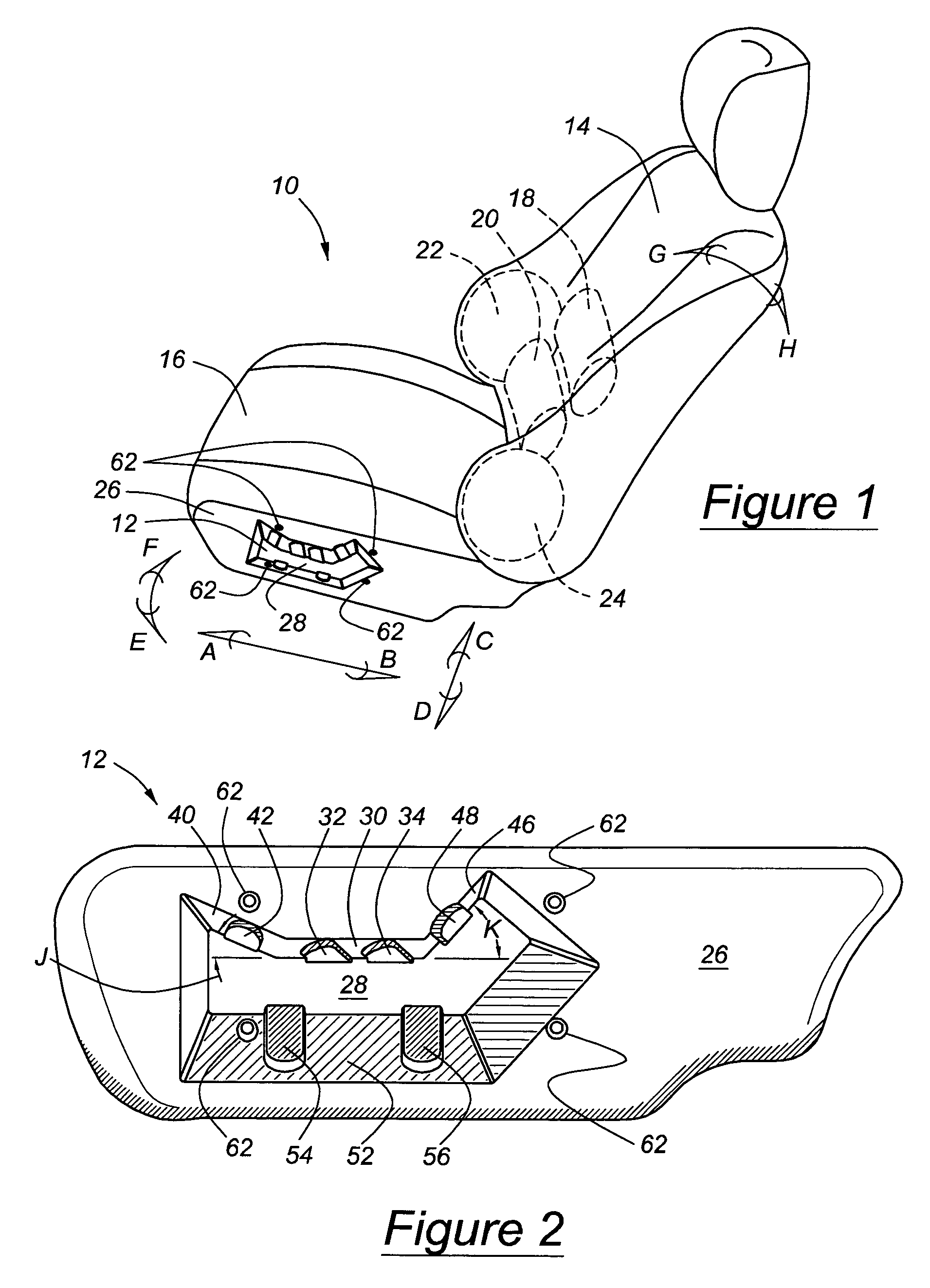
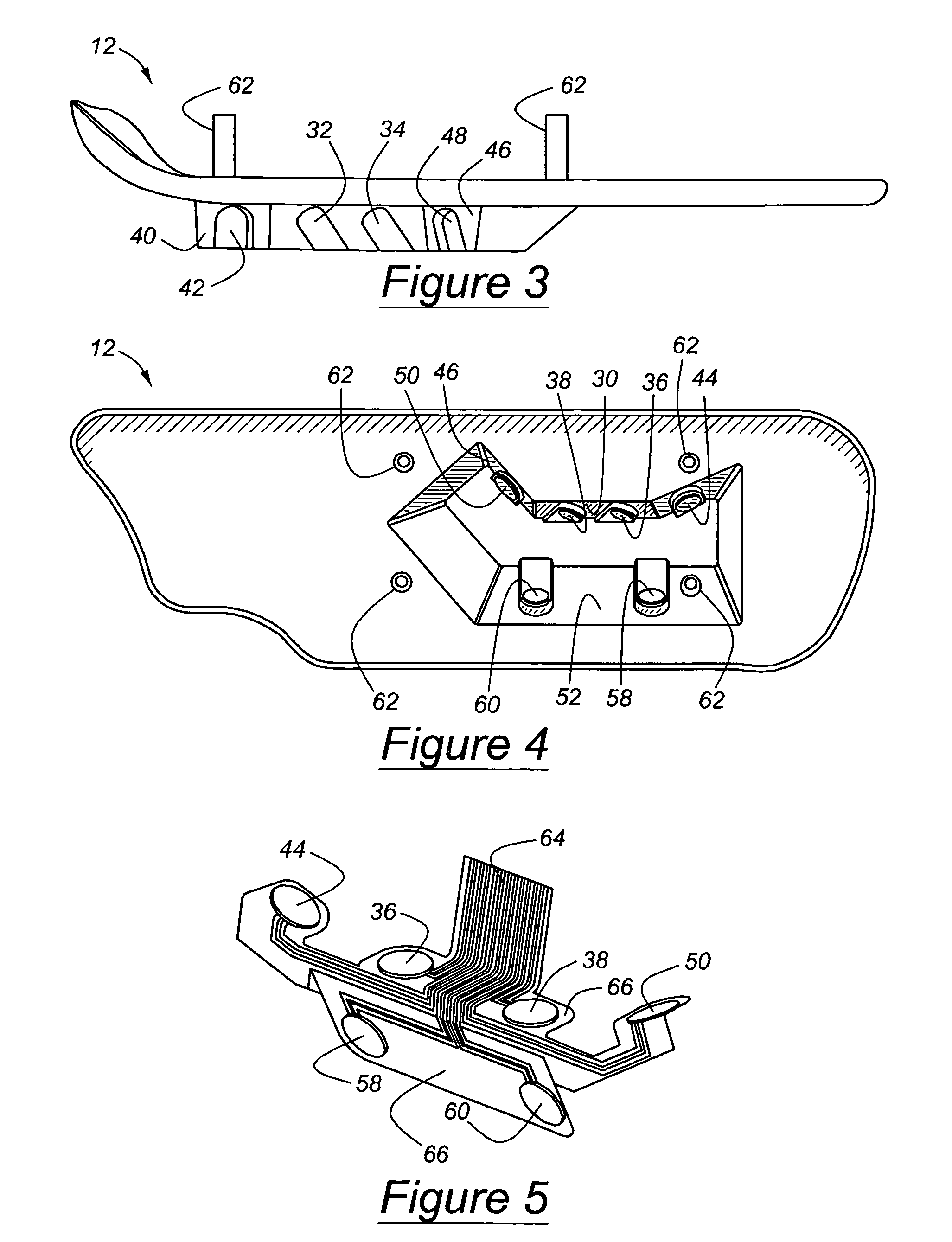
The present invention provides a power seat adjuster control with contactless sensors. The sensors control the motion of power seat drivers, which alter the position of the seat and the relative position of seat components. The control is located in a seat side shield readily accessible to a seated operator without need for direct sight of the controller. The control requires no manual force to activate it and no visual clues to operate it. Its operation is intuitive and ergonomic. The controller includes a seat adjuster with a base panel, a stepped panel extending laterally from a surface of the base panel, and selector areas inclined with respect to and extending between the base panel and the stepped panel and along at least a portion of a periphery of the stepped panel. Multiple spaced depressions are formed on an outer surface of the selector areas, with a contactless sensor secured to each depression, each sensor selectively producing a signal representing a seat adjustment function. The depressions on the outer surface of the controller provide the operator with visual and tactile indications of the corresponding sensor's location on the inner surface of the seat adjuster. The location of each sensor on the control panel corresponds intuitively to the function produced by the corresponding sensor.

Problems solved by technology

The piezoelectric element may generate electrical charges when mechanically distorted, which usually is caused by pressure or vibration exerted on the piezoelectric element.
However, a drawback with using a piezoelectric element for vehicle sensor actuation is that vibrations from the vehicle or road surfaces may result in an unintended sensor actuation.
Because the capacitive sensors are typically mounted under the surface of the fascia unit, activation of a sensor may occur when an object is inadvertently placed on or in close proximity to the sensor.
This ultimately can lead to activation of a device that was not intended.
Furthermore, if the capacitive sensors are placed in close proximity to one another, overlapping electrical fields may occur which may also lead to activation of a sensor adjacent to the sensor intended for activation.

Method used


Image

  • Contactless intuitive seat adjuster control
  • Contactless intuitive seat adjuster control
  • Contactless intuitive seat adjuster control

Examples


Embodiment Construction

[0021]Referring now to the drawings, there is illustrated in FIG. 1 a power seat assembly 10 for a motor vehicle, to which a seat adjuster control panel 12 of this invention may be applied. The seat assembly 10 includes a cushioned back 14, a cushioned seat 16, upper and lower lumbar supports 18, 20, and inner and outer lateral supports 22, 24. The seat assembly is moved as a unit forward and rearward A-B, upward and downward C-D automatically by motors in response to selections made through a seat adjuster control panel 12, mounted preferably on the seat side shield adjacent an outboard surface of the seat assembly. The seat shield is located in a space between the inside door panel and the outer later surface of the seat assembly. The tilted disposition E-F of the seat assembly 10 is also adjusted automatically by motors, which alternately raise and lower the front and rear of the seat 14. Similarly, the seat back 14 is tilted forward and backward G-H in relation to the cushioned ...


PUM


Abstract

A controller for selectively adjusting a power seat includes a seat adjuster including a base panel, a stepped panel extending laterally from a surface of the base panel, selector areas inclined with respect to and extending between the base panel and the stepped panel and along at least a portion of a periphery of the stepped panel. Multiple spaced depressions are formed on an outer surface of the selector areas. A contactless sensor is secured to an inner surface of the selector areas at each a depression, each sensor selectively producing a signal representing a seat adjustment function.

Description

BACKGROUND OF THE INVENTION[0001]The invention relates to a control for adjusting a power seat. More particularly, the invention pertains to a control panel containing sensors, which activate a seat adjustment mechanism without requiring tactile contact.DESCRIPTION OF THE RELATED ART[0002]Vehicle seat adjuster control devices typically require displacing a control knob by rotation or translation, depressing a control button, or sliding a mechanical or electro-mechanical control sensor to operate various electric motors that adjust the seat position, tilt the seat, and adjust the location and disposition of the seat surface relative to the seat back.[0003]In addition to push button switches, piezoelectric elements have been used for seat adjuster user interfaces, touch pads and sensors. Piezoelectric elements exhibit a dielectric change when tension or compression mechanically distorts the piezoelectric element. The piezoelectric element may generate electrical charges when mechanica...

Claims


Application Information

Patent Timeline
Patent Type & Authority Patents(United States)
IPC IPC(8): H01H9/00B60N2/02B60N2/66B60N2/90
CPCB60N2/0228B60N2/4415B60N2/449B60N2/66B60N2/914B60N2/99B60N2/665B60N2210/12B60N2/0239B60N2210/48H01H13/84H01H2217/04
Inventor SCHMIDT, ROBERT M.WRIGHT, JAMES B.BANTER, CHARLES B.
Owner LEAR CORP
Learn More