High pressure and temperature seal for downhole use

a technology of high pressure and seals, applied in the field of seals, can solve the problems of affecting the reliability of the seal, and reducing the service life of the seal, so as to prevent the collapse of the spring and seal

Inactive Publication Date: 2008-07-22
BAKER HUGHES HLDG LLC
View PDF29 Cites 28 Cited by
  • Summary
  • Abstract
  • Description
  • Claims
  • Application Information

AI Technical Summary

Benefits of technology

[0009]A seal for use in temperature and pressure extremes is disclosed. It features springs internal to the sealing members and the ability to seal against pressure differentials from opposed directions. A spacer ring prevents contact from oppositely oriented seal components and at the same time prevents spring and seal collapse under extreme loading conditions. The seal assembly is self-centering in a downhole seal bore and can be used on tools delivered on wireline, where the insertion forces available are at a minimum. The seal can withstand pressure differentials in excess of 13,500 PSI and temperatures above 350 degrees Fahrenheit.

Problems solved by technology

Under more severe temperature or / and pressure conditions, the presently known designs have been tested and have failed to perform reliably.
This means that insertion forces are limited because minimal force can be transmitted from the surface through wireline.
Clearly if the interference is too great the insertion, particularly with a wireline, will become problematic.
On the other hand, reducing the interference can result in seal failure under the proposed extreme conditions of pressure and temperature.
Tests at pressure extremes of over 13,500 PSI and temperatures above 350 degrees Fahrenheit revealed that this design was unsuitable for reliable service.
This design of FIG. 2 showed improved performance in high temperature and pressure conditions but was not to be the final solution.

Method used


Image

  • High pressure and temperature seal for downhole use
  • High pressure and temperature seal for downhole use
  • High pressure and temperature seal for downhole use

Examples


Embodiment Construction

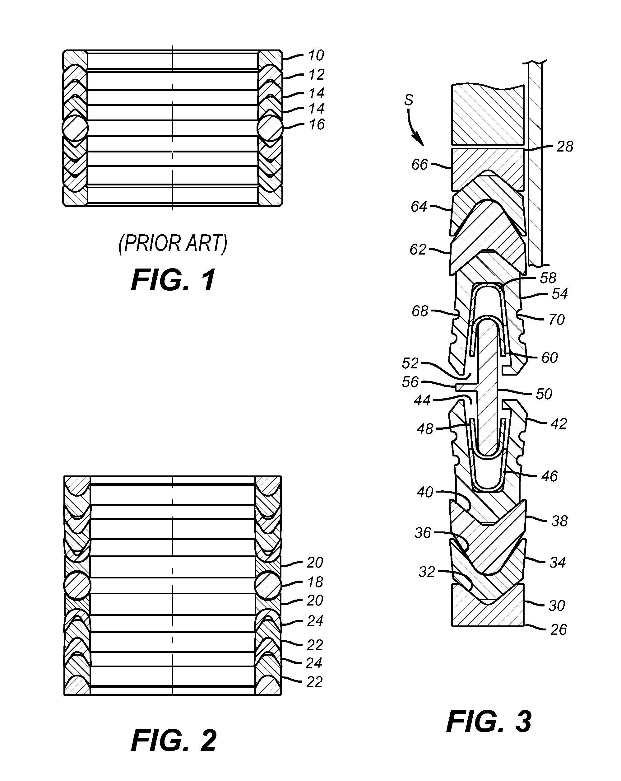
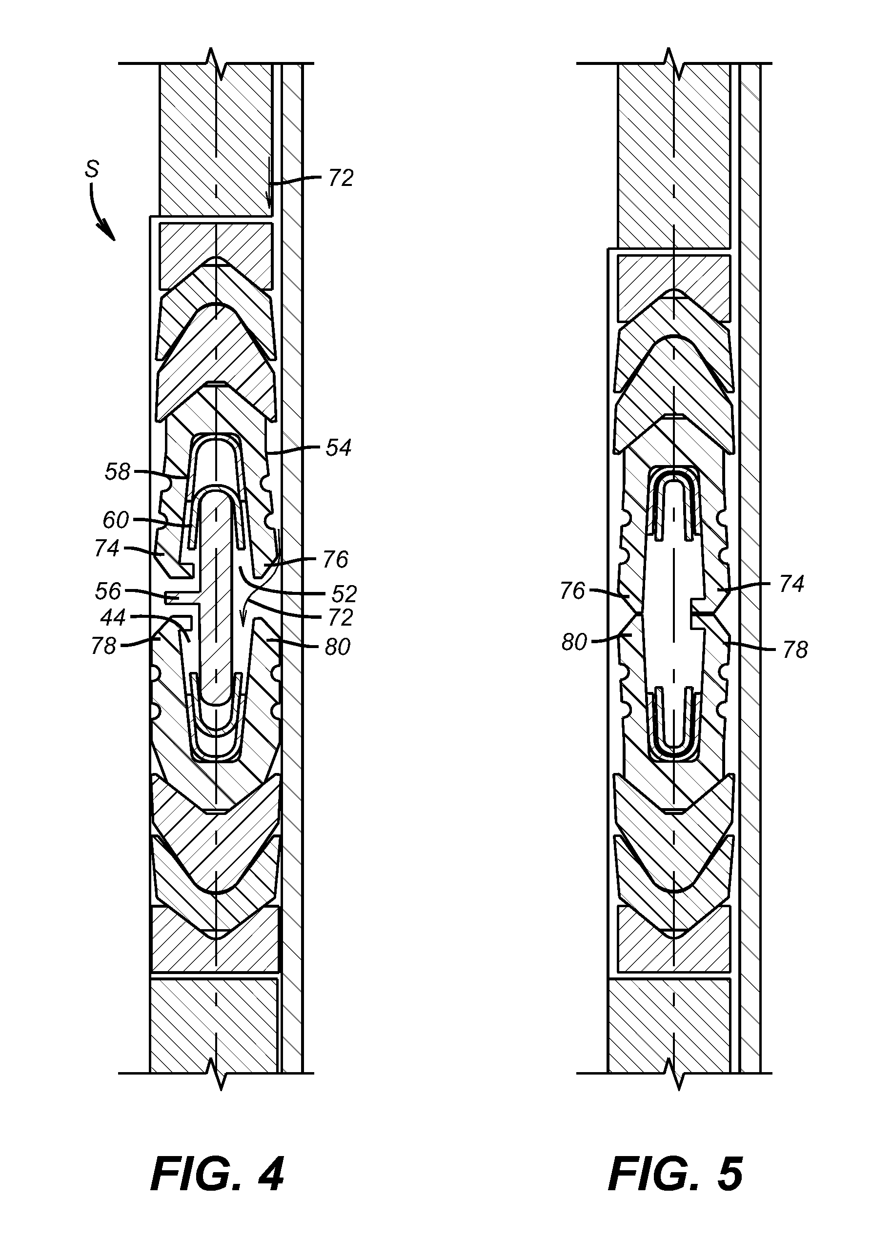
[0015]Referring to FIG. 3, the seal S of the present invention is shown without the tool that it would be secured to. The seal bore into which the seal S is to be inserted is also omitted on the basis that those skilled in the art are readily familiar with downhole tools and seal bores into which seals such as seal S are inserted. For similar reasons, the surface wireline equipment and the wireline are omitted due to their familiarity to the person skilled in this art. It should be noted that seal S can be used on a subsurface safety valve that can be delivered on wireline. This is only the preferred use and those skilled in the art will recognize that the seal S can be used with a broad variety of tools and delivered downhole in a variety of ways other than a wireline. Seal S is preferably used in applications of sealing in a seal bore downhole under conditions of high pressure and temperature differentials. Seal S can withstand differentials in pressure in either direction in exce...


PUM

PropertyMeasurementUnit
temperaturesaaaaaaaaaa
temperatureaaaaaaaaaa
temperaturesaaaaaaaaaa

Abstract

A seal for use in temperature and pressure extremes is disclosed. It features springs internal to the sealing members and the ability to seal against pressure differentials from opposed directions. A spacer ring prevents contact from oppositely oriented seal components and at the same time prevents spring and seal collapse under extreme loading conditions. The seal assembly is self-centering in a downhole seal bore and can be used on tools delivered on wireline, where the insertion forces available are at a minimum. The seal can withstand pressure differentials in excess of 13,500 PSI and temperatures above 350 degrees Fahrenheit.

Description

PRIORITY INFORMATION[0001]This application is a continuation application claiming priority from U.S. patent application Ser. No. 10 / 443,489, filed on May 22, 2003, which claims the benefit of U.S. Provisional Application No. 60 / 384,601, filed on May 30, 2002.FIELD OF THE INVENTION[0002]The field of this invention is a seal for use in temperatures of over 300 degrees Fahrenheit and over 10,000 pounds per square inch (PSI) and more particularly a seal adapted for wireline use where insertion forces are limited.BACKGROUND OF THE INVENTION[0003]Currently, in downhole applications, there are different types of seals to handle high temperature and pressure applications. The present limits of service of these designs are roughly about 350 degrees Fahrenheit and about 13,500 PSI. Under more severe temperature or / and pressure conditions, the presently known designs have been tested and have failed to perform reliably.[0004]Depending on the application, there are different types of seals for ...

Claims


Application Information

Patent Timeline
Patent Type & Authority Patents(United States)
IPC IPC(8): E21B33/128E21B33/00E21B33/12
CPCE21B33/1208E21B2033/005E21B2200/01F16J15/181F16J15/3236
Inventor WILLIAMS, RONALD D.WELCH, JR., EDWARD WAYNE
Owner BAKER HUGHES HLDG LLC
Why Eureka
Try Eureka