Card, manufacturing method of card, and thin type battery for card

a manufacturing method and card technology, applied in the field of cards, can solve the problems of difficult to completely prevent the breakdown of the battery seal by adjusting the pres condition, and the information saved in the ic card cannot be read without a reader/writer, so as to achieve the effect of suppressing the breakdown of the battery seal

Inactive Publication Date: 2006-10-26
NGK SPARK PLUG CO LTD
View PDF8 Cites 32 Cited by
  • Summary
  • Abstract
  • Description
  • Claims
  • Application Information

AI Technical Summary

Benefits of technology

[0019] According to the method of the invention, the card can be heated and laminated so that the spacer may be deformed elastically. As a result, a static load is always applied to the thin type battery, and it is firmly fixed in the card. M

Problems solved by technology

The former is excellent because it is not necessary to consider the battery life, but the information saved in the IC card cannot be read without a reader/writer.
In this heating and laminating process, a large pressure may be applied to the battery that breaks down the seal, and the electrode active material may leak out.
In the heating and laminating process of manufacturing an IC card, the press condition is set at a lower temperature and a lower pressure than in a conventional manufacturing method for a magnetic card, but it is hard to completely prevent breakdown of a battery seal by adju

Method used


Image

  • Card, manufacturing method of card, and thin type battery for card
  • Card, manufacturing method of card, and thin type battery for card
  • Card, manufacturing method of card, and thin type battery for card

Examples


second embodiment

[0054] An IC card 101 shown in FIG. 6 is an example of a spacer 27 of sheet form having rubber elasticity adjusted in size to be received in a cavity 79 and, being inserted to contact tightly between a main body 12 of a thin type battery 1 and a second oversheet 72. The size of the spacer 27 is preferably adjusted to contact with the entire surface of the main body 12. The constituent material for the spacer 27 is preferably an elastomer having a proper heat resistance, such as silicone resin. The heat resistance allows mutual adhesion of oversheets 74, 75, inner sheet 73, and core sheet 72, but not allow fusion at the heating and laminating temperature for obtaining IC card 101. The thin type battery 1, oversheets 74, 75, inner sheet 73, and core sheet 72 are the same as mentioned above.

[0055] The heating and laminating step for fabricating the IC card 101 may be preferably done in a temperature range for allowing mutual adhesion of oversheets 74, 75, inner sheet 73, and core shee...

third embodiment

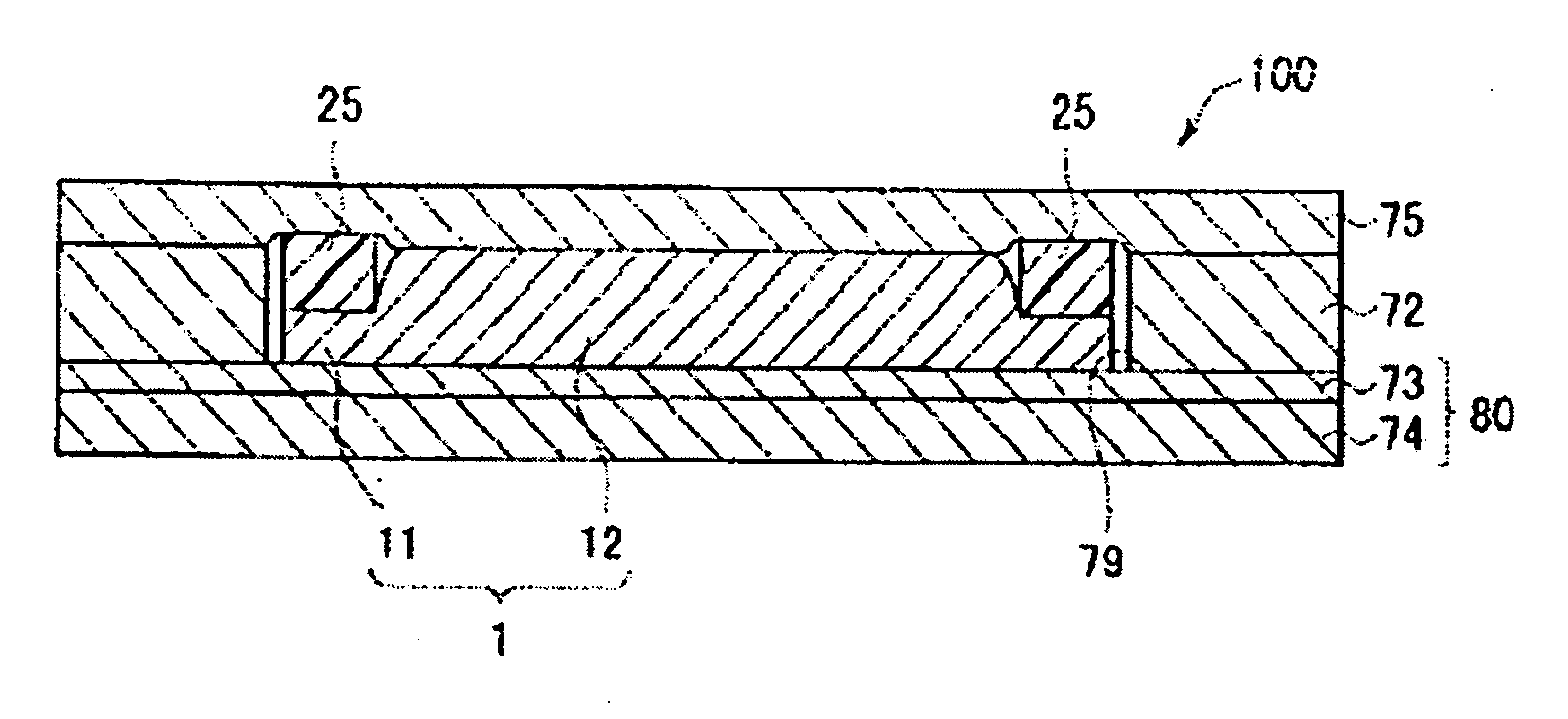
[0056] In an IC card 102 shown in FIG. 7, a spacer sheet 29 is provided that has an opening 29a dimensioned to receive main body 12 of thin type battery 1, but not allow receipt of seal section 11. Spacer sheet 29 is inserted between a second oversheet 75 and a core sheet 76. The spacer sheet 29 is composed as a sheet member to be integrally adhered to the second oversheet 75 and core sheet 76. An opening peripheral edge 29b of the spacer sheet 29 is adhered to the seal section 11 of the thin type battery 1 at the first side, and to the oversheet 75 at the second side. In other words, a stepped cavity is formed by the core sheet 76 and spacer sheet 29, and the thin type battery 1 is accommodated within the stepped cavity. The thin type battery 1, oversheets 74, 75, and inner sheet 73 are the same as mentioned above. The core sheet 76 is dimensioned thinner than the thin type battery 1 in order to insert the spacer 29.

[0057] The spacer sheet 29 can be composed of the same resin mate...


PUM


Abstract

The invention presents a method for manufacturing an IC card with a built-in battery where the seal of the battery does not breakdown during a heating and laminating process. The manufacturing method for the IC card of the invention includes accommodating a thin type battery 1 in a cavity 79 formed by overlaying an inner sheet 73 and a first oversheet 74 on a core sheet 72 having a penetration pole 79a. A second oversheet 75 covers the cavity 79, and a spacer 25 is inserted between a seal section 11 of the thin type battery 1 and second oversheet 75. Pressure and heat are applied to mutually adhere the sheets, wherein the pressing force is applied to the seal section 11 by way of the spacer 25.

Description

FIELD OF THE INVENTION [0001] The present invention relates to a card, a manufacturing method of a card, and a thin type battery for a card. BACKGROUND OF THE INVENTION [0002] As magnetic cards are being replaced by other storage mediums, a card (also called IC card) incorporating a storage device or microcomputer is receiving significant attention. Methods of supplying power for saving information or executing operations includes a method of making use of electromotive force by electromagnetic induction, and a method of supplying power from a built-in battery. The former is excellent because it is not necessary to consider the battery life, but the information saved in the IC card cannot be read without a reader / writer. An internal battery is needed if operated using a display unit such as a liquid crystal panel. By combining these two power supply methods, power can be supplied stably, and the IC card can be used for multiple functions. [0003] The battery built in the IC card must...

Claims


Application Information

Patent Timeline
IPC IPC(8): G06K19/06
CPCG06K19/077G06K19/0702
Inventor GOTO, TOMOHISAHARADA, SADAMITSU
Owner NGK SPARK PLUG CO LTD
Why Eureka
Try Eureka