RFID tag and RFID tag production method

a technology of rfid tags and production methods, applied in the direction of mechanical actuation of burglar alarms, instruments, and mechanical details of semiconductor/solid-state devices, can solve problems such as failures in which rfid tags break, and achieve the effect of suppressing failures

Inactive Publication Date: 2008-02-21
FUJITSU LTD +1
View PDF10 Cites 24 Cited by
  • Summary
  • Abstract
  • Description
  • Claims
  • Application Information

AI Technical Summary

Benefits of technology

[0025]According to this RFID tag production method of the present invention, an RFID tag according to the present invention that suppresses the occurrence of failures such as a breakage can be easily produced.

Problems solved by technology

An RFID tag has sections that are structurally vulnerable to tensile stress, such as a connection part between an antenna and a circuit chip, and when a tensile stress is produced by changes in shape that are transmitted to the RFID tag from the article, there is a fear of a failure occurring in which the RFID tag breaks.

Method used


Image

  • RFID tag and RFID tag production method
  • RFID tag and RFID tag production method
  • RFID tag and RFID tag production method

Examples


Embodiment Construction

[0039]Embodiments of the present invention will be described below with reference to the drawings.

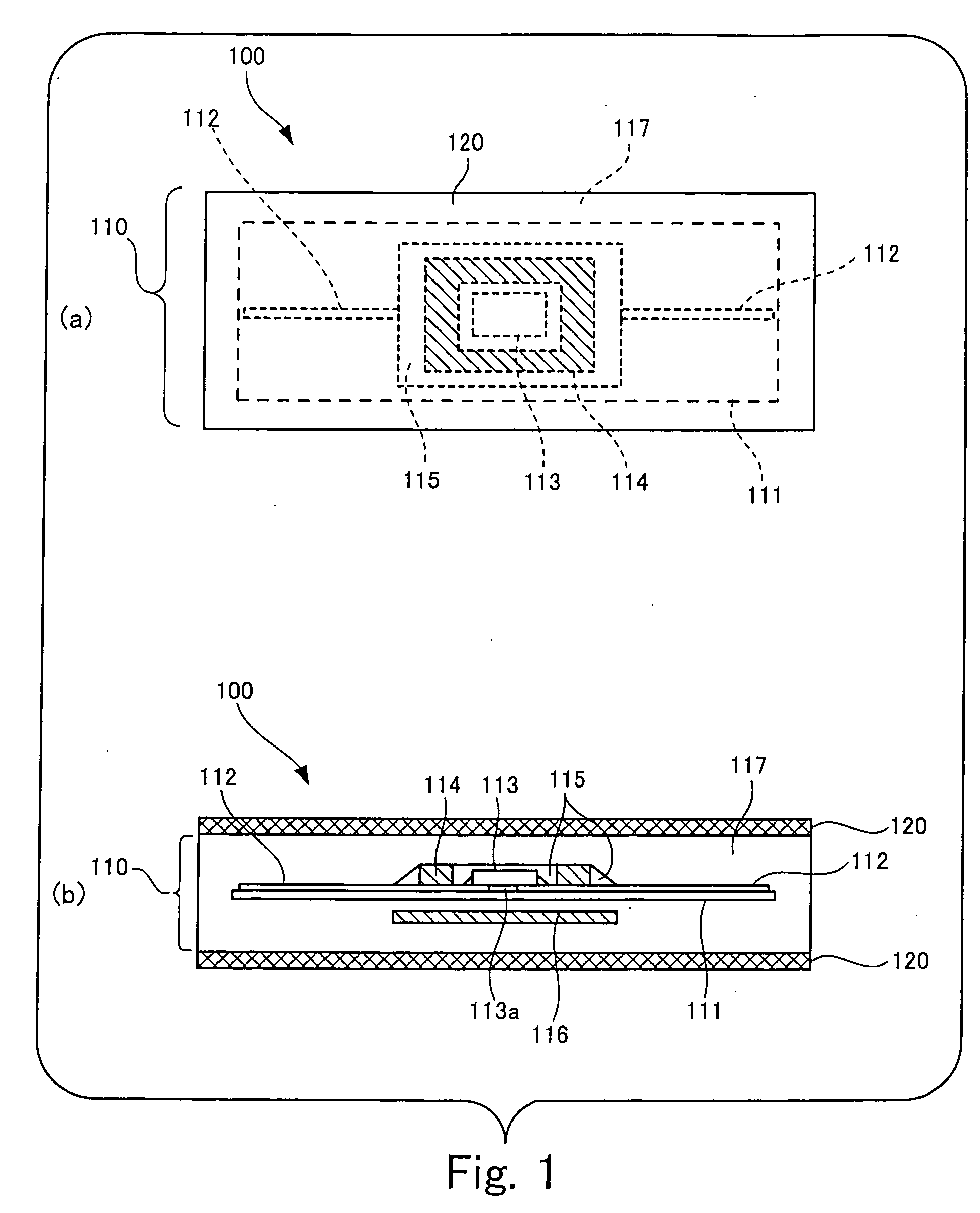
[0040]FIG. 1 is a schematic diagram that illustrates an embodiment of an RFID tag according to the present invention.

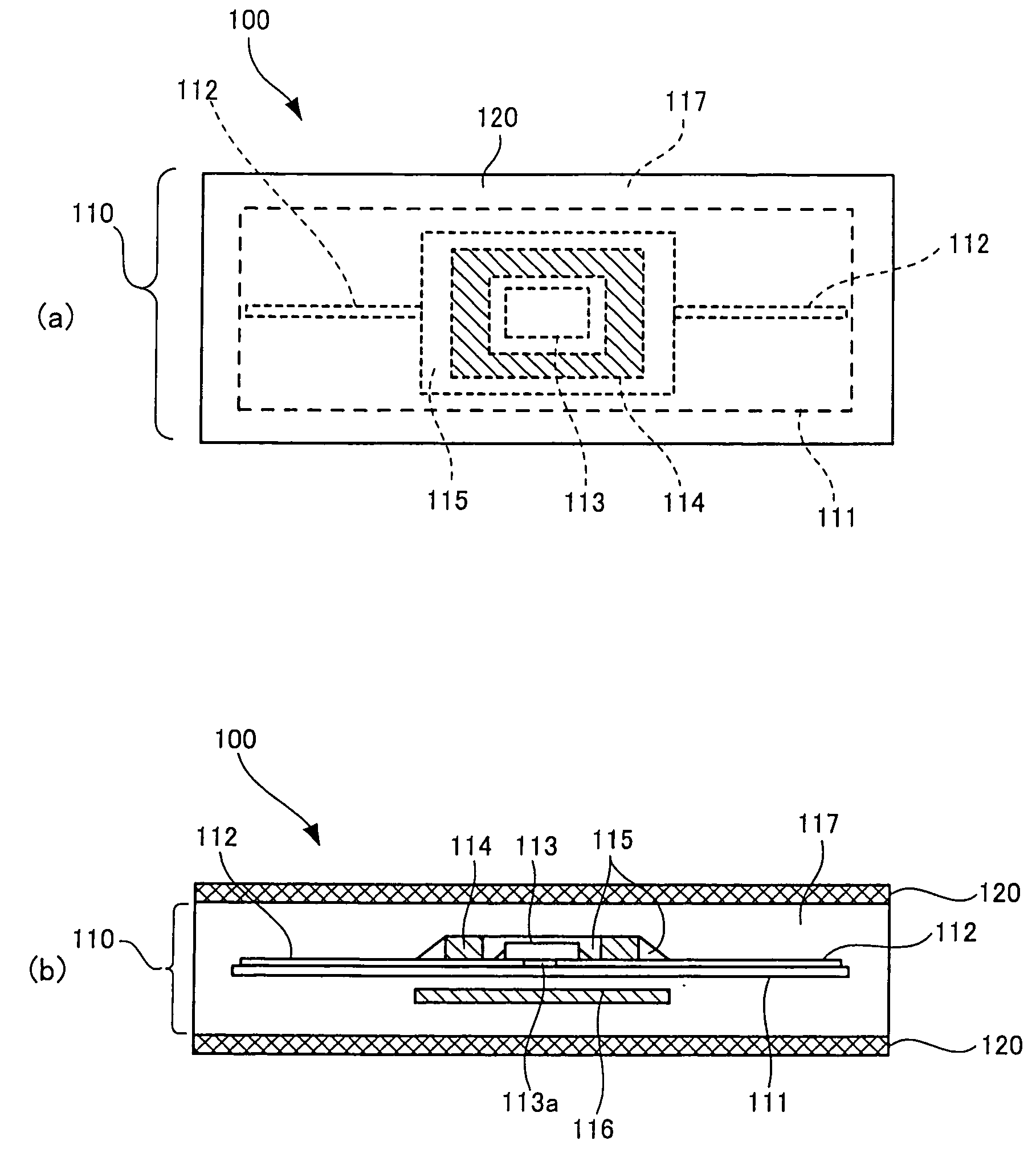
[0041]Part (a) of FIG. 1 is a top view of an RFID tag 100 as an embodiment of the RFID tag according to the present invention, in which the inner structure of the RFID tag is shown in a transparent state and part (b) of FIG. 1 shows a cross section in the longitudinal direction of the RFID tag 100.

[0042]The RFID tag 100 shown in FIG. 1 is an RFID tag which it is assumed will be attached to an article that changes shape easily, such as clothing. The RFID tag 100 has a main unit 110 that consists of a base 111 that is formed with PET film; a communication antenna 112 that is wired on the base 111; a circuit chip 113 that is electrically connected to the antenna 112 and is adhered and fixed to the base 111 by an adhesive 113a and carries out radio communication via the anten...


PUM

PropertyMeasurementUnit
shapeaaaaaaaaaa
tensile stressaaaaaaaaaa
degree of adhesivenessaaaaaaaaaa

Abstract

The RFID tag includes: a main unit consisting of a base, a communication antenna that is wired on the base, a circuit chip that is electrically connected to the antenna and performs radio communication via the antenna, a chip reinforcing member covering the periphery of the circuit chip, an underside reinforcing member that is disposed at a position that sandwiches the base with respect to the chip reinforcing member, and a rubber cover member that covers these components; and protective layers that sandwich the main unit from the front and rear sides and have greater slipperiness than the slipperiness between the main unit and a contactant.

Description

BACKGROUND OF THE INVENTION[0001]1. Field of the Invention[0002]The present invention relates to an RFID (Radio Frequency Identification) tag which exchanges information with an external device in a non-contact manner, and an RFID tag production method that produces that kind of RFID tag. Note that this “RFID tag” may also be referred to as a “wireless IC tag”.[0003]2. Description of the Related Art[0004]Various types of RFID tags that exchange information with an external device, typically represented by a reader / writer, in a non-contact manner using radio waves have been proposed in recent years (for example, see Japanese Patent Laid-Open No. 2000-311176, Japanese Patent Laid-Open No. 2000-200332, and Japanese Patent Laid-Open No. 2001-351082). An RFID tag in which a circuit chip and a radio wave communication antenna pattern are mounted on a base sheet made of plastic or paper has been proposed as one type of such RFID tag. This type of RFID tag is designed to be used in a mode i...

Claims


Application Information

Patent Timeline
Patent Type & Authority Applications(United States)
IPC IPC(8): G08B13/14H01L23/02H01L23/28
CPCG06K19/027G06K19/07749G06K19/07728G06K19/077G06K19/07
Inventor BABA, SHUNJIHASHIMOTO, SHIGERUSUGIMURA, YOSHIYASUNIWATA, TSUYOSHI
Owner FUJITSU LTD
Why Eureka
Try Eureka