Heat exchanger

a heat exchanger and fin-tube technology, applied in the direction of tubular elements, lighting and heating apparatus, stationary conduit assemblies, etc., can solve the problems of difficult repair and failure of brazing, and achieve the effect of easy repair work

Inactive Publication Date: 2007-07-26
DENSO CORP
View PDF16 Cites 23 Cited by
  • Summary
  • Abstract
  • Description
  • Claims
  • Application Information

AI Technical Summary

Benefits of technology

[0013]The present invention has been accomplished in view of the above points. An object of the present invention is to provide a heat exchanger capable allowing easy repairing work at the time of the occurrence of a failure when brazing plates which compose a tube while the occurrence of a failure to brazing the tube to a header plate is being suppressed.
[0015]According to the present invention, in the portion except for the engagement portion, the first edge portion of the plate is located in a portion on the outer wall face where the outer fin is not provided. Since the first edge portion of the plate is distant from the outer fin, it is possible to enhance the working property of the repairing work at the time of the occurrence of a failure of brazing the plates.
[0016]According to the present invention, in the engagement portion, the first edge portion of the plate is located at a position in which the outer wall face of the tube is composed of continuous face. Accordingly, it is possible to suppress the occurrence of a failure of brazing the tube to the header plate.

Problems solved by technology

However, in the case where the tube is divided into two pieces, the following problems may be encountered.
Accordingly, at the time of brazing, a brazing failure may occur.
However, when the tube 2 is composed as described above, the following problems may be encountered.
Therefore, it is difficult to conduct repairing.
The above problems are caused not only in the tube composed in such a manner that the tube is formed out of two divided plates but also in the tube composed in such a manner that the tube is formed out of one plate and both edge portions of the one plate, which are opposed mutually, are engaged mutually so that the tube can be formed.

Method used


Image

  • Heat exchanger
  • Heat exchanger
  • Heat exchanger

Examples


first embodiment

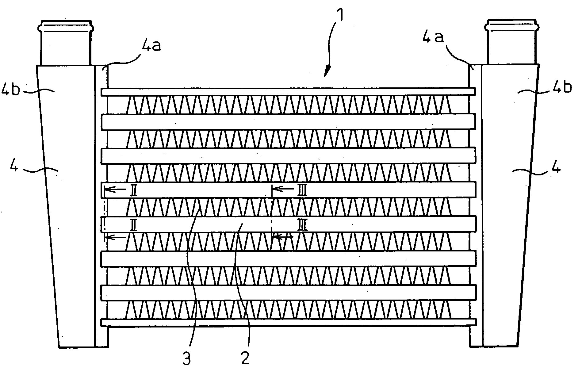
[0035]FIG. 1 is an overall arrangement view showing a heat exchanger of the first embodiment of the present invention. In this embodiment, explanations are made into an example in which the heat exchanger of the present invention is applied to an inter-cooler. In this connection, although not shown in the drawing, the inter-cooler described in the present embodiment is arranged on the downstream side of a suction air current of a supercharger which pressurizes suction air sucked into an internal combustion engine so as to cool the suction air by exchanging heat between the suction air and a cooling wind.

[0036]As shown in FIG. 1, the inter-cooler 1 is a fin-and-tube-type heat exchanger and includes: a plurality of tubes 2 arranged in parallel mutually; and outer fins 3 arranged between the tubes 2 which are adjacent mutually. The inter-cooler 1 further includes header tanks 4 arranged on both end sides in the longitudinal direction of the tubes 2. In this connection, in FIG. 1, the l...

second embodiment

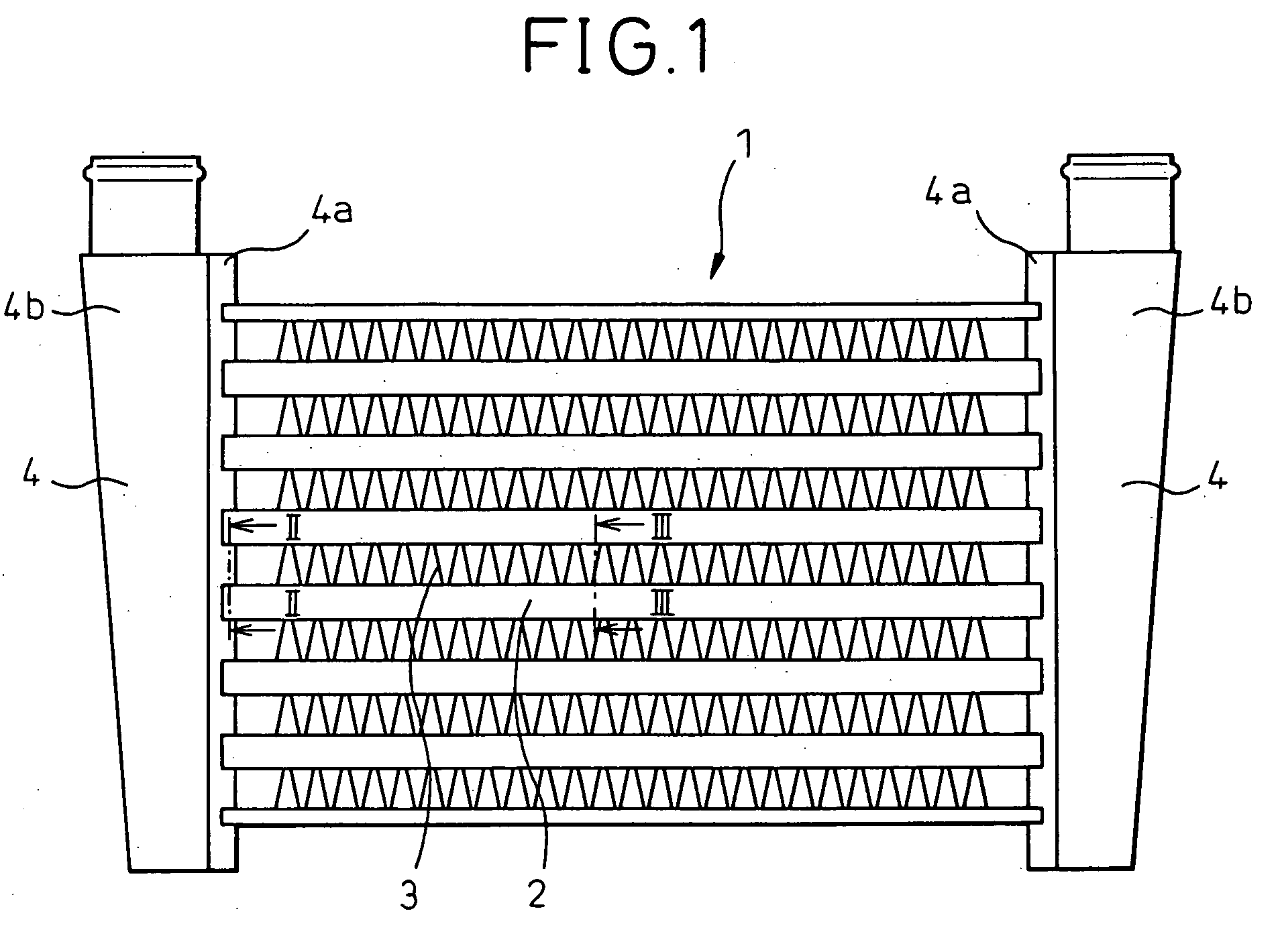
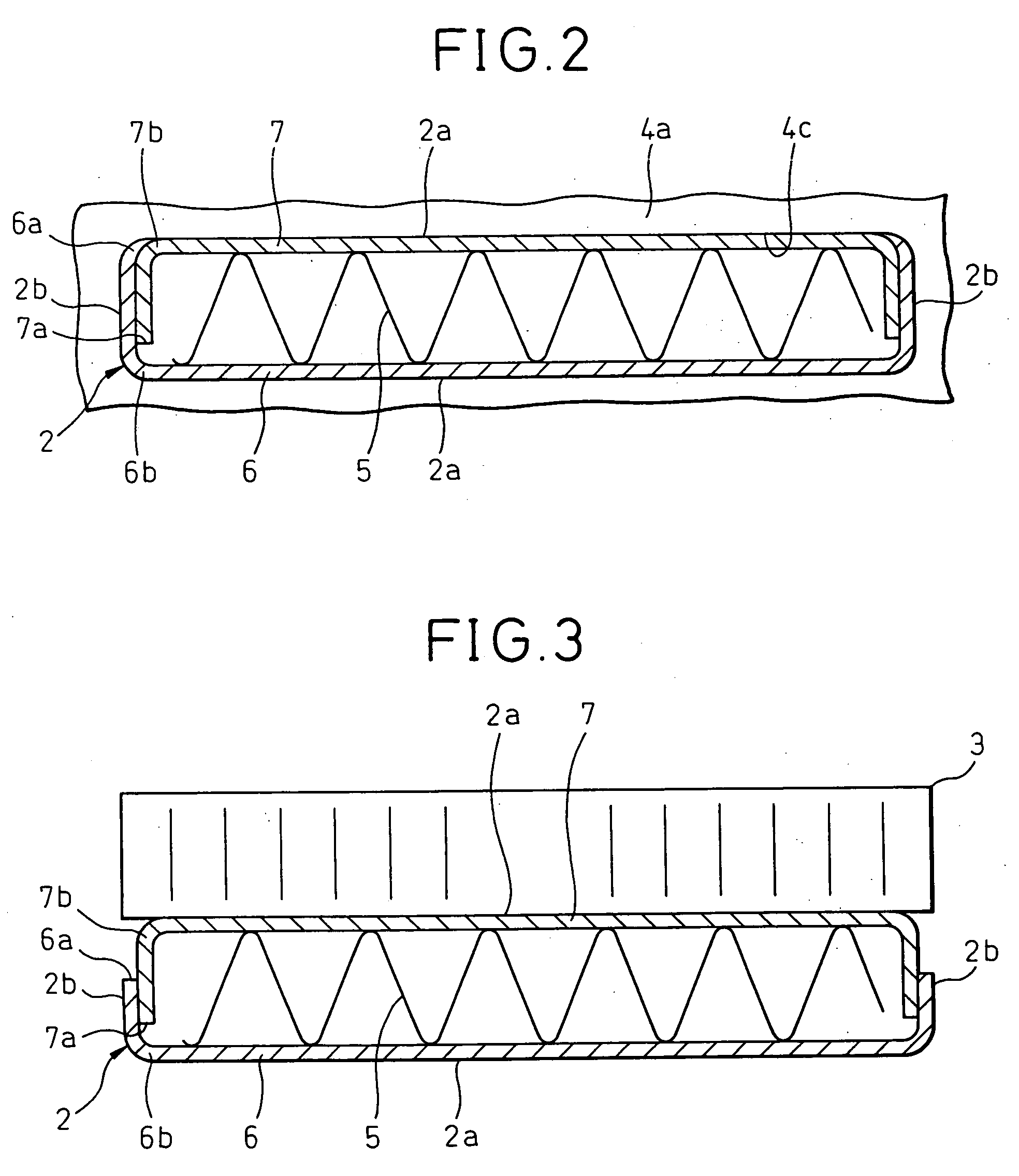
[0067]FIGS. 9 and 10 are lateral sectional views showing a tube of the second embodiment of the present invention. FIG. 9 is a sectional view taken on line II-II in FIG. 1. FIG. 10 is a sectional view taken on line III-III in FIG. 1. Like reference characters are used to indicate like parts in FIGS. 2, 3, 9 and 10.

[0068]As shown in FIGS. 2 and 3, in the tube 2 of the first embodiment, the lateral cross-sectional shape is symmetrical in the lateral direction. However, as shown in FIGS. 9 and 10, in the tube 2 of the present embodiment, the lateral cross-sectional shape is not symmetrical in the lateral direction. That is, in the tube 2 of the present embodiment, on the left of the tube 2 in the drawing, in the same manner as that of the first embodiment, the first plate 6 is located outside. However, on the right of the tube 2 in the drawing, and different from the first embodiment, the second plate 7 is located outside.

[0069]In this case, only the right of the tube 2 in the drawing ...

third embodiment

[0072]FIGS. 11 and 12 are lateral sectional views of the tube of the third embodiment of the present invention. In this connection, FIG. 11 is a sectional view taken on line II-II in FIG. 1. FIG. 12 is a sectional view taken on line III-III in FIG. 1. Like reference characters are used to indicate like parts in FIGS. 2, 311 and 12.

[0073]In the present embodiment, as shown in FIGS. 11 and 12, one flat tube 2 is composed of one plate 8. Concerning this plate 8, on the side 2b of the tube 2, while the first edge portion 8a of the plate 8 is being located outside the second edge portion 8b, the first edge portion 8a side of the plate 8 and the second edge portion 8b side are put on mutually. This portion in which the first edge portion 8a side of the plate 8 and the second edge portion 8b side are put on mutually is joined by means of brazing.

[0074]This plate 8 is formed into a shape described as follows. As shown in FIG. 11, in the region C of the tube 2, the first edge portion 8a is l...


PUM

PropertyMeasurementUnit
distanceaaaaaaaaaa
shapeaaaaaaaaaa
displacementaaaaaaaaaa

Abstract

A tube 2 is composed of a first plate 6 and a second plate 7 which are opposed and engaged with each other. In a region C on both end sides of the tube 2, the first plate 6 is formed into a shape in which an edge portion 6a of the first plate is laid along a bent portion 7b of the second plate so that an outer wall face of the tube will be composed of continuous face. In a region D except for both end sides of the tube 2, the first plate 6 is formed into a shape in which the edge portion 6a of the first plate 6 is laid between the edge portion 7a of the second plate 7 and the bent portion 7b.

Description

BACKGROUND OF THE INVENTION[0001]1. Technical Field of the Invention[0002]The present invention relates to a fin-and-tube-type heat exchanger, in the tube of which an inner fin is provided. The fin-and-tube-type heat exchanger of the present invention is preferably used for an inter-cooler for cooling suction air of an internal combustion engine and can also be used for a condenser for emitting the heat of a thermal medium of an air conditioner.[0003]2. Description of the Related Art[0004]In a conventional tube of a heat exchanger into which an inner fin is incorporated, a set of plates are engaged with each other so that an inner fin can be interposed between them, as described in the official gazette of JP-A-2003-28586 (FIGS. 6 and 8). In the case where the tube is divided into two pieces as described above, at the time of forming the tube, it is easy to incorporate the fin into the tube.[0005]However, in the case where the tube is divided into two pieces, the following problems m...

Claims


Application Information

Patent Timeline
Patent Type & Authority Applications(United States)
IPC IPC(8): F28F1/40F28F1/36
CPCF28D1/05366F28F1/04F28F1/128Y10T29/49378Y10T29/49364Y10T29/49384Y10T29/4935F28F3/025
Inventor WATANABE, HARUHIKOSAKO, YUUJINAKATA, KYOUJIROU
Owner DENSO CORP
Why Eureka
Try Eureka