Flexible printed circuit board

Inactive Publication Date: 2005-09-13
ACHILLES CORP
View PDF11 Cites 26 Cited by
  • Summary
  • Abstract
  • Description
  • Claims
  • Application Information

AI Technical Summary

Benefits of technology

[0010]Therefore, with the foregoing in mind, it is an object of the present invention to provide a flexible printed c

Problems solved by technology

The head suspension assembly with the above-mentioned constitution has a problem of ESD (electrostatic discharge) of the magnetic head.
Therefore, the flexible printed circuit board is likely to be charged by applying friction generated during handling.
Therefore, they are very sensitive to electrostatic discharge (breakdown).
The static electricity generated during such a

Method used


Image

  • Flexible printed circuit board
  • Flexible printed circuit board
  • Flexible printed circuit board

Examples


example 1

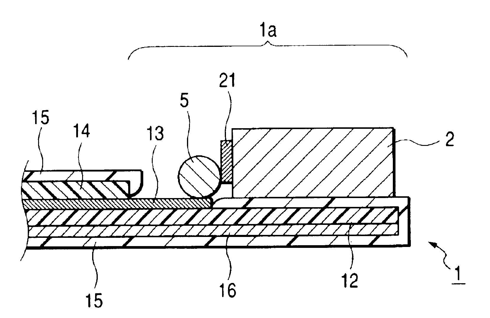
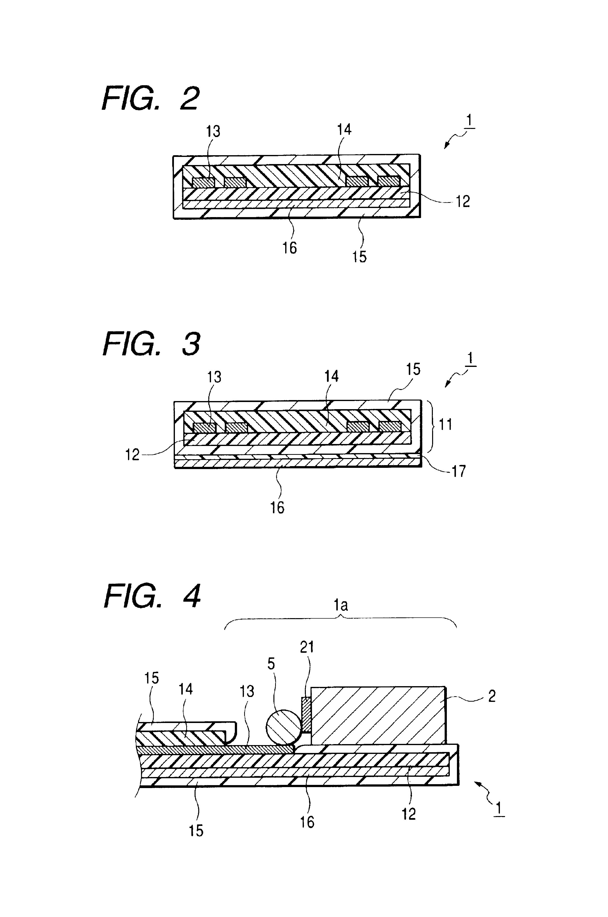
[0058]A stainless layer made of a stainless foil was coated with polyimide varnish to form a base layer. Four conductive circuits made of copper were formed on the base layer by lithography. A gold thin film was formed on the conductive circuits. Thereafter, a cover layer made of polyimide was formed on the base layer and the conductive circuits to produce a laminate (substrate body). The cover layer was formed by lithography, and the conductive circuits were exposed in a magnetic head connecting portion and an end to be a substrate unit side, whereby connecting portions were formed.

[0059]Then, 500 ml of a 0.1 mol / L potassium peroxydisulfate aqueous solution was placed in a 1 L glass beaker and held at 2° C. to 3° C., and the above-mentioned laminate was soaked in the solution. Thereafter, 100 ml of a 0.2 mol / L pyrrole aqueous solution was added to the potassium peroxydisulfate aqueous solution, and the resultant mixture was stirred for 10 minutes at 15° C. to form a conductive poly...

example 2

[0063]Four conductive circuits made of copper were formed on a base layer made of polyimide by lithography. A gold thin film was formed on the conductive circuits. Thereafter, a cover layer made of polyimide was formed on the base layer and the conductive circuits to produce a laminate (substrate body). The cover layer was formed by lithography, and the conductive circuits were exposed in a magnetic head connecting portion and an end to be a substrate unit side, whereby connecting portions were formed.

[0064]Then, 500 ml of a 0.1 mol / L potassium peroxydisulfate aqueous solution was placed in a 1 L glass beaker and held at 2° C. to 3° C., and the above-mentioned laminate was soaked in the solution. Thereafter, 100 ml of a 0.2 mol / L pyrrole aqueous solution was added to the potassium peroxydisulfate aqueous solution, and the resultant mixture was stirred for 10 minutes at 15° C. to form a conductive polymer layer. Then, the resultant laminate was ultrasonically washed with water.

[0065]...

example 3

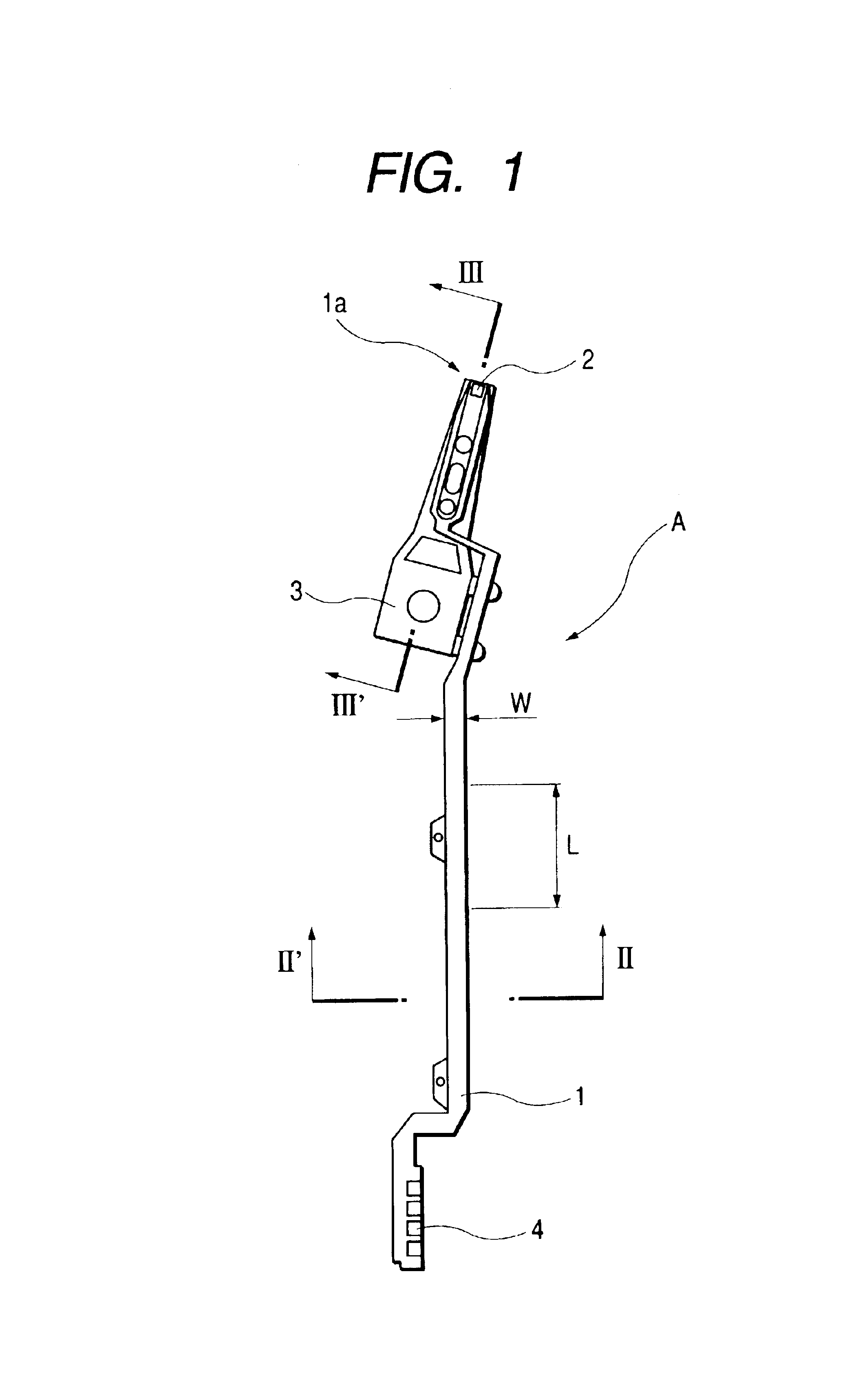
[0069]A flexible printed circuit board of the present invention having a full length of about 30 mm, a width of about 1 mm, and a thickness of about 0.5 mm was produced in the same way as in Example 1. The thickness of the conductive polymer layer was set to be 0.07 μm on the cover layer.

[0070]Furthermore, as shown in Test Example 4, it was confirmed that the conductive polymer layer was not present or substantially absent on the surface of the conductive circuits in the magnetic head connecting portion.


PUM


Abstract

A flexible printed circuit board of the present invention directly relays connecting portions of a magnetic head placed on a suspension to connecting portions of a base end of a carriage arm in a head suspension assembly of a magnetic disk apparatus. The flexible printed circuit board includes a laminate composed of at least a base layer, a plurality of conductive circuits formed on the base layer, a cover layer covering the conductive circuits, and a conductive polymer layer formed in the insulating material portion in the surface of the laminate. The flexible printed circuit board includes a stainless layer below the base layer or on a lower side of the conductive polymer layer on the base layer side. More preferably, in the magnetic head connecting portion, the cover layer is not formed, and on the base layer in the magnetic head connecting portion, a conductive polymer layer is formed, whereas on the plurality of conductive circuits in the magnetic head connecting portion, the conductive polymer layer is not present or is substantially absent, if any, to such a degree as to allow the magnetic head to be electrically connected to the conductive circuits.

Description

BACKGROUND OF THE INVENTION[0001]1. Field of the Invention[0002]The present invention relates to a flexible printed circuit board used for a head suspension assembly of a magnetic disk apparatus. More specifically, the present invention relates to a flexible printed circuit board capable of sufficiently preventing electrostatic discharge of a magnetic head even when a head suspension assembly is configured using a magnetic head with high performance.[0003]2. Description of the Related Art[0004]A magnetic disk apparatus widely used as a storage apparatus for a computer generally includes, as main components, a magnetic disk that is a recording medium, a spindle motor for rotating the magnetic disk, a head suspension assembly including a magnetic head, a carriage arm for supporting the head suspension assembly, a servo apparatus for moving the carriage arm, and a substrate unit for processing an electric signal. The head suspension assembly is composed of a magnetic head for recording...

Claims


Application Information

Patent Timeline
IPC IPC(8): G11B5/48H05K1/02H05K1/00H05K3/28H05K3/32H05K1/05
CPCG11B5/4853H05K1/0259H05K1/0393H05K1/056H05K3/28H05K3/328H05K2201/0329H05K2201/10234H05K2203/0285G11B5/40
Inventor KAGEYAMA, TERUYOSHIOKINO, SHINYAITO, MAMORU
Owner ACHILLES CORP
Why Eureka
Try Eureka