Precision targeting system for firearms

a precision targeting and firearm technology, applied in the field of precision targeting, can solve the problems of gyroscopic systems, inconvenient operation, and inability to accurately target,

Inactive Publication Date: 2008-07-29
BAE SYST INFORMATION & ELECTRONICS SYST INTERGRATION INC
View PDF19 Cites 38 Cited by
  • Summary
  • Abstract
  • Description
  • Claims
  • Application Information

AI Technical Summary

Benefits of technology

[0007]It is therefore an object of one or more embodiments of the present invention to provide a precision targeting

Problems solved by technology

However, movements of the desired target and/or movements by the marksman may cause imprecise targeting and consequent missing of the target when the firearm is discharged.
There are at least two drawbacks to such gyroscopic systems however.
First, they only correct movements of th

Method used


Image

  • Precision targeting system for firearms
  • Precision targeting system for firearms
  • Precision targeting system for firearms

Examples


Embodiment Construction

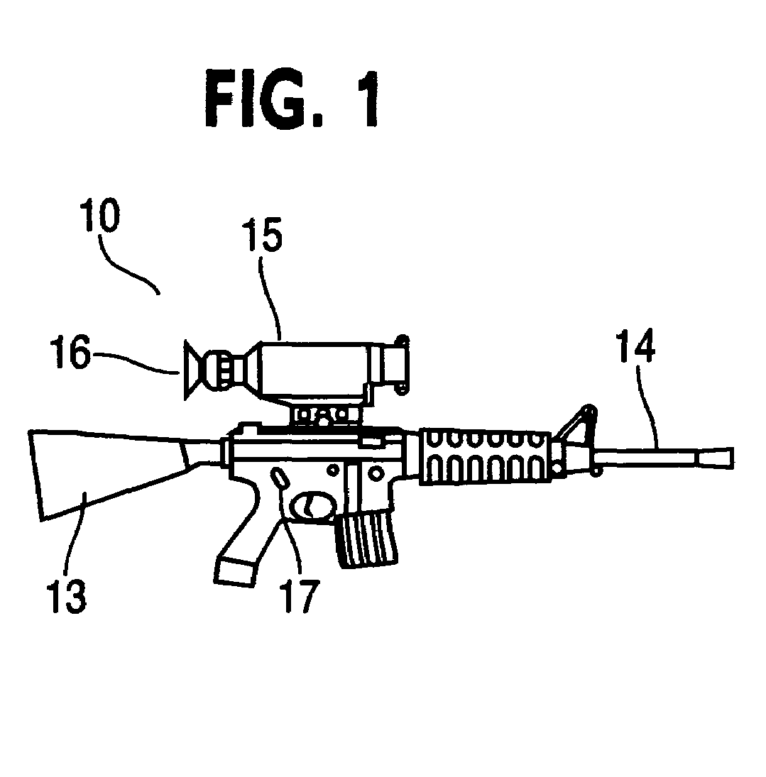
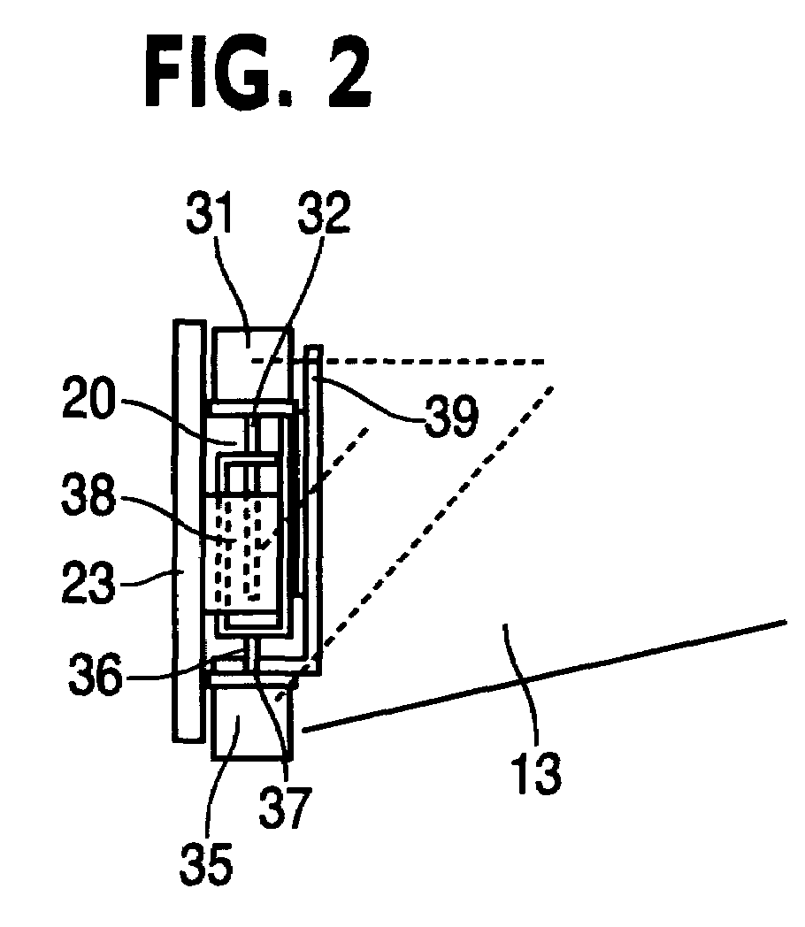
[0005]In one embodiment, the present invention is a processor-based precision targeting module for firearms. The precision targeting module works in conjunction with an image capturing sight or scope on the firearm. The invention has an actuator system that receives signals from the processor and adjusts the aim of the firearm. A marksman first identifies an object of interest in the sight. In one embodiment, the marksman indicates to the precision targeting module that he is attempting to lock onto the target, and the module displays on the firearm sight how accurate the marksman is. After any necessary adjustments by the marksman, the marksman again indicates to the system that he would like to lock onto the target. In another embodiment, the marksman sets his firearm sight onto the object of interest, and the image processing of the system automatically locks onto the object. In either embodiment, after the system locks onto the object of interest, the sight captures the image an...


PUM


Abstract

A precision targeting system for a firearm has an image capturing scope, a processor, and an actuator. In one embodiment, a user indicates when he wants to lock onto the target, and then readjust his aim after receiving feedback from the system. In another embodiment, the system automatically locks onto the target. After lock on, the system compares successive images, and determines if the target has moved in the firearm sight. If movement has occurred, the system calculates the degree of the movement, and sends appropriate signals to an actuator which corrects the aim of the firearm. The system thereby converts reasonably good aim into precision aim.

Description

FIELD OF THE INVENTION[0001]The present invention relates to precision targeting, and in particular, an intelligent processor-based precision targeting system for firearms.BACKGROUND OF THE INVENTION[0002]In military and law enforcement situations, marksmen and their firearms are expected to provide accurate and precise targeting at both short and long ranges. However, movements of the desired target and / or movements by the marksman may cause imprecise targeting and consequent missing of the target when the firearm is discharged.[0003]Prior efforts to solve these problems all have their shortcomings. For example, some systems use gyroscopic technologies to combat these problems. In such systems, a gyroscope is implanted into the body or stock of a firearm. The marksman aims at the intended target, and locks the system onto the target by indicating to the system in some manner that the intended target is in the sight of the firearm. After that indication and locking onto the target, ...

Claims


Application Information

Patent Timeline
IPC IPC(8): F41G1/00
CPCF41G1/38F41G5/06F41G3/16F41G1/473
Inventor PAGE, EDWARD A.
Owner BAE SYST INFORMATION & ELECTRONICS SYST INTERGRATION INC
Why Eureka
Try Eureka