Terminal contact and clamp assembly for a cable terminal block and method for processing the same

Active Publication Date: 2008-07-29
WU CHIH YUAN
View PDF5 Cites 43 Cited by
  • Summary
  • Abstract
  • Description
  • Claims
  • Application Information

AI Technical Summary

Benefits of technology

[0020]A terminal contact and clamp assembly in accordance with the present invention has a cage clamp and an inner contact. The cage clamp has a top, a bottom, a through hole, multiple bottom teeth and at least one protruding tooth. The bottom has an inner bottom surface. The bottom teeth are formed on the inner bottom surface. The at least one protruding tooth is formed on and protrudes up from the inner bottom surface and has a top end higher than the inner bottom surface. The inner contact is mounted in the through hole.

Problems solved by technology

However, the conventional method has following disadvantages.
However, when the wire core is a multi-core, the contact and clamp assembly hardly bites and holds the multi-core and the cable easily slip out of the contact and clamp assembly.

Method used


Image

  • Terminal contact and clamp assembly for a cable terminal block and method for processing the same
  • Terminal contact and clamp assembly for a cable terminal block and method for processing the same
  • Terminal contact and clamp assembly for a cable terminal block and method for processing the same

Examples


Embodiment Construction

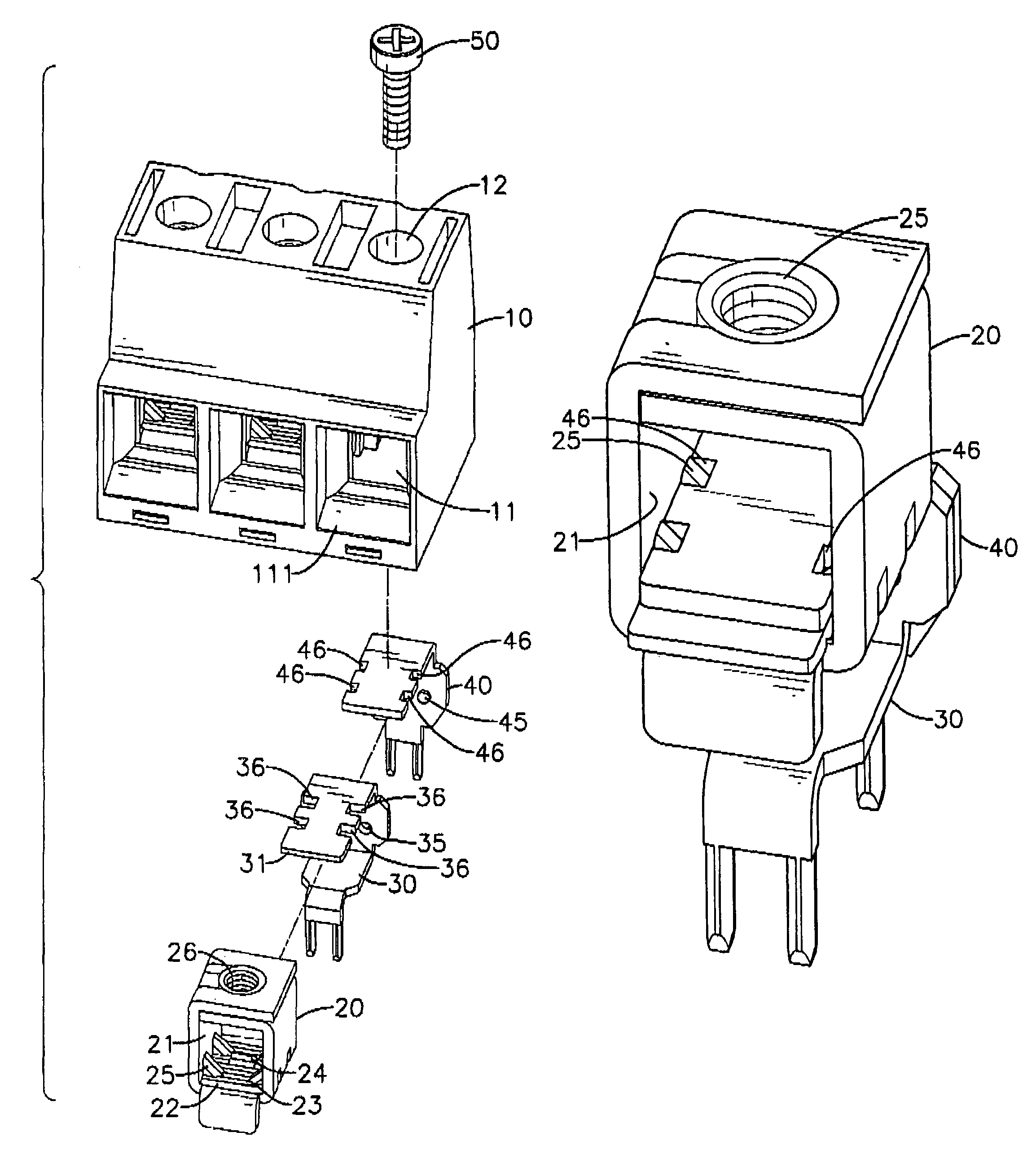
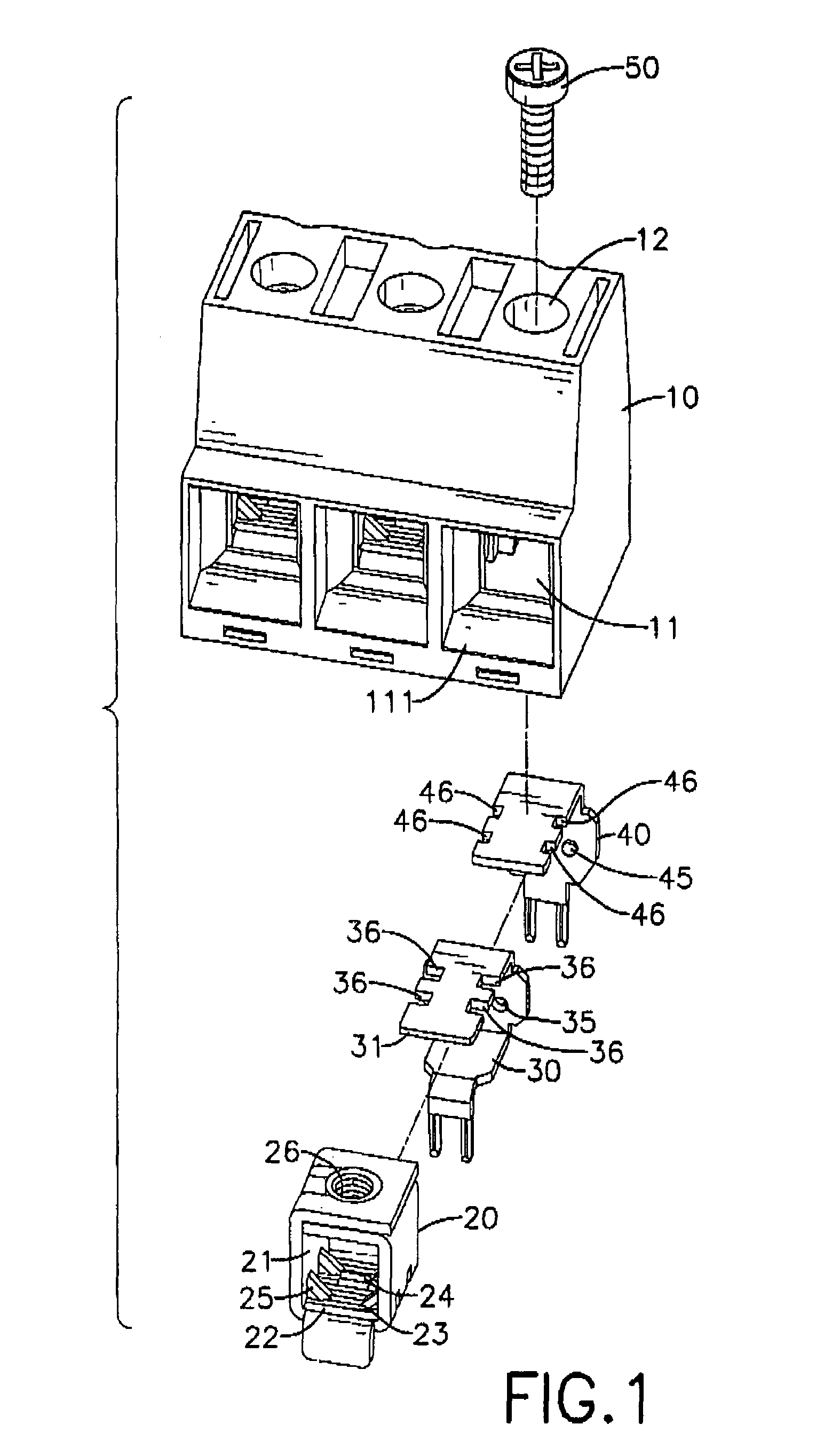
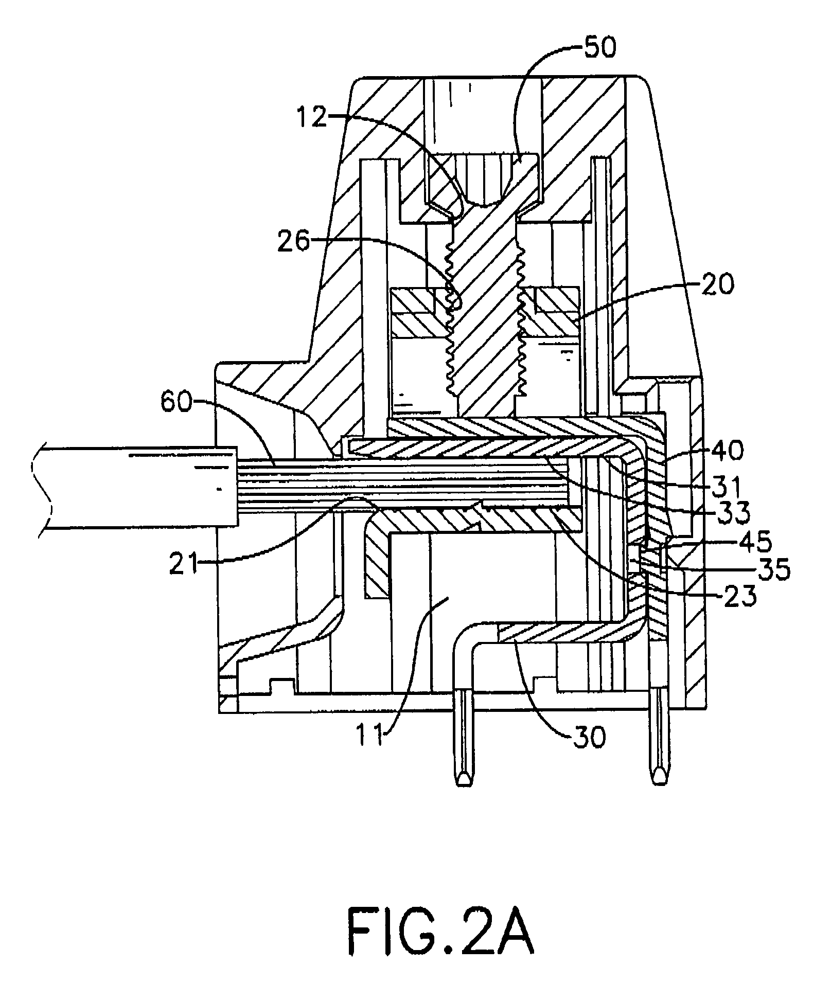
[0038]With reference to FIGS. 1, 2A, 2B and 3A, terminal contact and clamp assemblies for a cable terminal block are mounted in a casing (10) of the cable terminal box. The casing (10) has a front, a top, multiple cavities (11) and multiple mounting holes (12). The cavities (11) are defined in the front of the casing (10), respectively accommodate the terminal contact and clamp assemblies and each cavity (11) has a front opening (111) to allow a cable (60) to extend in the cavity (11). The mounting holes (12) are defined in the top and communicate respectively with the cavities (11).

[0039]Each terminal contact and clamp assembly comprises a cage clamp (20), an inner contact (30), an outer contact (40) and a bolt (50).

[0040]The cage clamp (20) being hollow, made of metal, mounted in one cavity (11) in the casing (10), is rectangular and has a front open end, a rear open end, a top, a bottom, a through hole (21), a threaded hole (26), multiple bottom teeth (23), at least one protrudin...


PUM


Abstract

A terminal contact and clamp assembly has a cage clamp and an inner contact. The cage clamp has a top, a bottom, a through hole multiple bottom teeth and at least one protruding tooth. The bottom has an inner bottom surface. The bottom teeth are formed on the inner bottom surface. The at least one protruding tooth is formed on and protrudes up from the inner bottom surface and has a top end higher than the inner bottom surface. The inner contact is mounted in the through hole. The at least one protruding tooth deeply bites an exposed wire core of a cable and prevents the cable from slipping out of the terminal contact and clamp assembly.

Description

[0001]The present invention is a continuation-in-part application of a U.S. patent application Ser. No. 11 / 730,601 filed on Apr. 3, 2007 now abandoned.BACKGROUND OF THE INVENTION[0002]1. Field of the Invention[0003]The present invention relates to a terminal contact and clamp assembly, and more particularly to a terminal contact and clamp assembly for a cable terminal block and a method for processing the terminal contact and clamp assembly. The terminal contact and clamp assembly securely and tightly bites and holds an exposed wire core at one end of a cable.[0004]2. Description of Related Art[0005]Cable terminal blocks are used generally in electronic devices for holding ends of cables so that the electronic devices are capable of transmitting power or electronic signals to other devices through the cables.[0006]With reference to FIGS. 7 and 8, a conventional cable terminal block comprises a casing (90) and a contact and clamp assembly.[0007]The casing (90) has a cavity (91) and a...

Claims


Application Information

Patent Timeline
Patent Type & Authority Patents(United States)
IPC IPC(8): H01R4/36
CPCH01R4/26H01R12/515H01R4/363H01R4/304
Inventor WU, CHIH-YUAN
Owner WU CHIH YUAN
Why Eureka
Try Eureka