Driving apparatus

a driving shaft and steering shaft technology, applied in the direction of piezoelectric/electrostrictive/magnetostrictive devices, electrical apparatus, piezoelectric/electrostrictive/magnetostriction machines, etc., can solve the problems of driving instability, inability to obtain the necessary operating speed, and occasionally dissolving of the resin component of the driving shaft, etc., to achieve the effect of eliminating the operation disabled state, improving the operating defect state, and eliminating the operation disabled

Inactive Publication Date: 2008-08-05
KONICA MINOLTA INC
View PDF13 Cites 321 Cited by
  • Summary
  • Abstract
  • Description
  • Claims
  • Application Information

AI Technical Summary

Benefits of technology

[0008]It is a main object of the present invention to provide a driving apparatus that is capable of improving an operating defective state of an impact actuator or eliminating an operation disabled state easily and securely.

Problems solved by technology

When, however, the actuator is driven for a long time in a high-temperature state (under generation of frictional heat), a resin component in the driving shaft occasionally dissolves.
For example, when the mobile object and the driving shaft are brought into the fastened state or the nearly fastened state as described above, under the environmental condition such that the force generated by the actuator becomes comparatively weak (for example, in a low-temperature state), a necessary operating speed cannot be obtained and thus the driving becomes unstable at the time of next driving (actuating), namely, the actuator is brought into an operation defective state.
Further, not only under the environmental condition such that the actuator is in the operation defective state, but also under the environmental condition at the time of normal driving, the actuator is brought into an operation disabled state such that it is not driven at all.

Method used


Image

  • Driving apparatus
  • Driving apparatus
  • Driving apparatus

Examples


Embodiment Construction

[0025]Embodiments of the present invention are explained below with reference to the drawings.

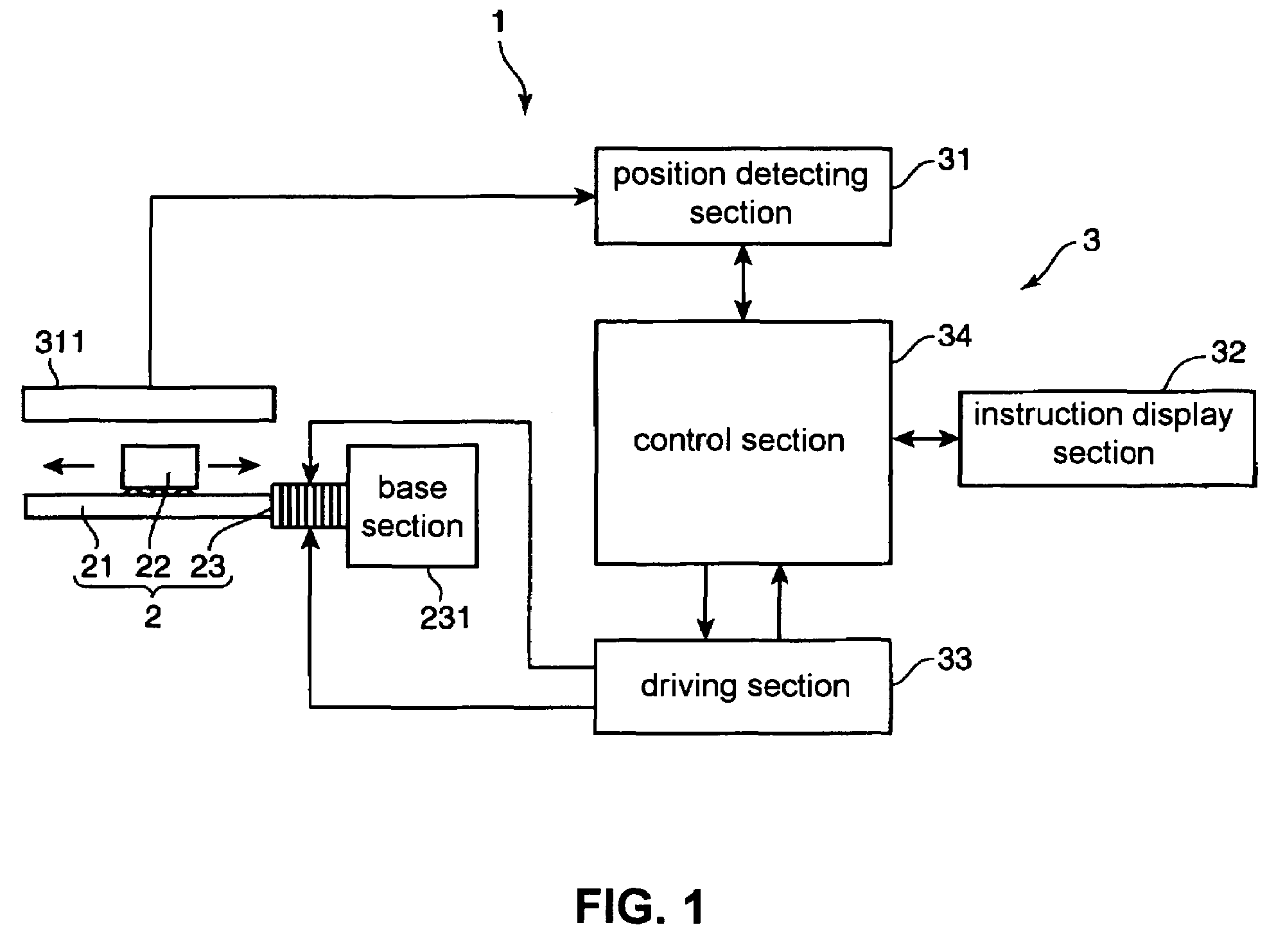
[0026]FIG. 1 is a block diagram illustrating one constitutional example of a piezoelectric driving apparatus according to the present invention. As shown in FIG. 1, the piezoelectric driving apparatus 1 is composed of a piezoelectric actuator 2 and a driving signal generating circuit 3. The piezoelectric actuator 2 is an impact actuator (linear actuator) where so-called ultrasonic driving is carried out. The piezoelectric actuator 2 has a rod section 21, a slider section 22, a piezoelectric element section 23 and the like.

[0027]The rod section 21 is a bar-shaped driving member (driving shaft) having a predetermined sectional shape that is driven (vibrated) by the piezoelectric element section 23, and supports a movement of the slider section 22. The slider section 22 is friction-bonded, namely, engaged with the rod section 21 by predetermined frictional force, and is a driven member (mobile...


PUM


Abstract

A determination is made whether a moving speed of a slider section with respect to a rod section in a piezoelectric actuator is lower than a predetermined speed. When the moving speed is lower than the predetermined speed, it is considered that a friction-bonded portion between the rod section and the slider section is in a fastened state or a nearly fastened state. A resonance frequency of the piezoelectric actuator or a frequency proximity to the resonance frequency is set as a driving frequency for the piezoelectric actuator. The slider section is moved in a reciprocating manner plural times with respect to the rod section. As a result, an abnormal state is eliminated from the piezoelectric actuator.

Description

[0001]The present application claims priority to Japanese Patent Application No. 2004-301519 filed in Oct. 15, 2004, the entire content of which is hereby incorporated by reference.BACKGROUND OF THE INVENTION[0002]1. Field of the Invention[0003]The present invention relates to a driving apparatus using an electromechanical transducer such as a piezoelectric element.[0004]2. Description of the Related Art[0005]Conventionally, impact driving system actuators (impact actuators), which are constituted so that a mobile object such as slider is friction-bonded to a rod-type driving member (driving shaft) so as to be mounted thereto and an electromechanical transducer such as a piezoelectric element is fastened to one end of the driving shaft, are known. For example, in a piezoelectric actuator disclosed in U.S. Pat. No. 6,433,459, a predetermined driving voltage is applied to a piezoelectric element so that the piezoelectric element and a driving shaft are displaced into a saw-tooth wave....

Claims


Application Information

Patent Timeline
Patent Type & Authority Patents(United States)
IPC IPC(8): H01L41/09
CPCH02N2/062H02N2/025
Inventor HARA, YOSHIHIRO
Owner KONICA MINOLTA INC
Why Eureka
Try Eureka