Dead bolt lock system having multiple security features

a technology of dead bolt locks and security features, applied in the field of dead bolt locks, can solve the problems of not being designed to exert the necessary pushing or pulling force, not being well suited to long-term use in this manner of safe lock bolts and actuating mechanisms, and not being able to achieve the necessary push or pull for

Inactive Publication Date: 2008-09-16
LOCKMASTERS
View PDF76 Cites 16 Cited by
  • Summary
  • Abstract
  • Description
  • Claims
  • Application Information

AI Technical Summary

Benefits of technology

[0023]The inventive dead bolt lock provides significant advantages over prior dead bolt locks. First, a dead bolt lock system of this invention can accept any conventional safe lock, e.g., a combination lock, mechanical lock or electro-mechanical lock, manufactured to a standard specification or, in other words, with a standard footprint. More specifically, one or more housings of the dead bolt lock system accept locks having a standard footprint, as is often required by government specifications. Moreover, the dead bolt lock system functions with a variety of security lock devices, including those using standard lock bolts which extend and retract linearly from the lock casing or locks using swing type bolts which pivot from the lock casing, for example, with a spring bias. In any case, however, the lock member or bolt does not apply or receive significant pushing or pulling force during operation of the dead bolt lock system. Because housing or support structure may be situated adjacent the lock member or bolt, and because of the torque override clutch, the system prevents significant side loads on the lock members or bolts. Security lock bolts generally are subjected to only side loads, either from the lock bolt testers as described above or from an unauthorized entry attempt. As another advantage of the invention, the security locks and access controls may be eliminated and the system will still function as a dead bolt passage set. In this type of use, for example, the lock down feature may still be a functional part of the system.

Problems solved by technology

One drawback of such devices is that safe lock bolts and actuating mechanisms may not be well suited for long term use in this manner.
In other words, they may not be designed to exert the necessary pushing or pulling force during extension and retraction of the dead bolt.
This feature enables quick exit from the secured area, however, it is not usually desirable to leave the door unlocked in this manner.
On the other hand, when the life safety feature is not enabled, the above-mentioned dead bolt knobs do not provide a particularly easy manner of escape for individuals with various disabilities.
It will be appreciated that this combination of a dead bolt lock and a doorknob lock makes it difficult to exit the secured area.
Again, disabled individuals may have problems when trying to exit through such a door, particularly in the event of an emergency.
Further, many lock systems are vulnerable to opening through the application of shock loads, such as during an attempted unauthorized forced entry.
For example, a shock load can cause a handle to rotate under its own weight potentially withdrawing a dead bolt and opening a door.
Similarly, the application of a shock load can cause the dead bolt to move of its own initiative.
For example, a heavy blow delivered to the dead bolt lock or door may cause the dead bolt, because of inertia, to retract into a retracted position in which the lock system is unlocked.
Hence, the dead bolt lock is susceptible to unauthorized opening by a person familiar with their construction.

Method used


Image

  • Dead bolt lock system having multiple security features
  • Dead bolt lock system having multiple security features
  • Dead bolt lock system having multiple security features

Examples


Embodiment Construction

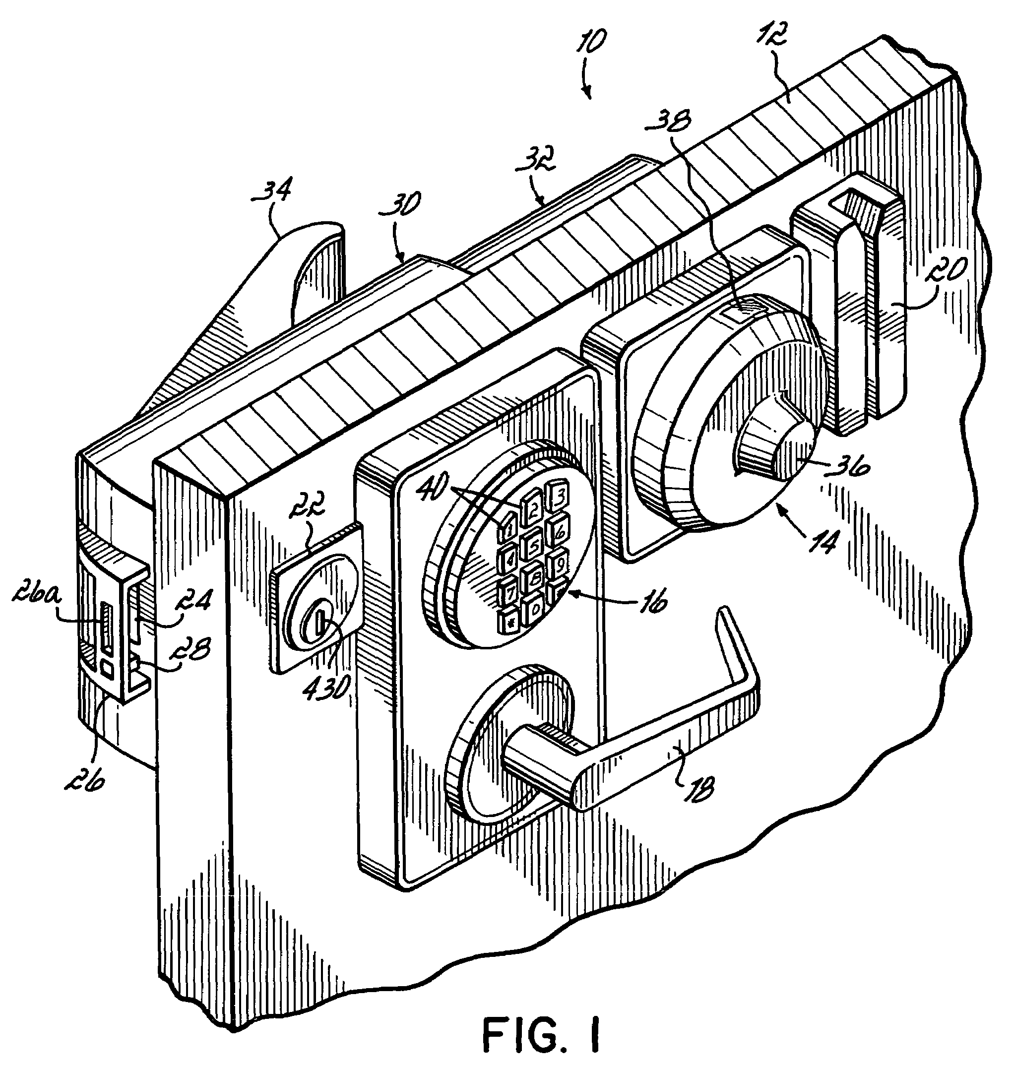
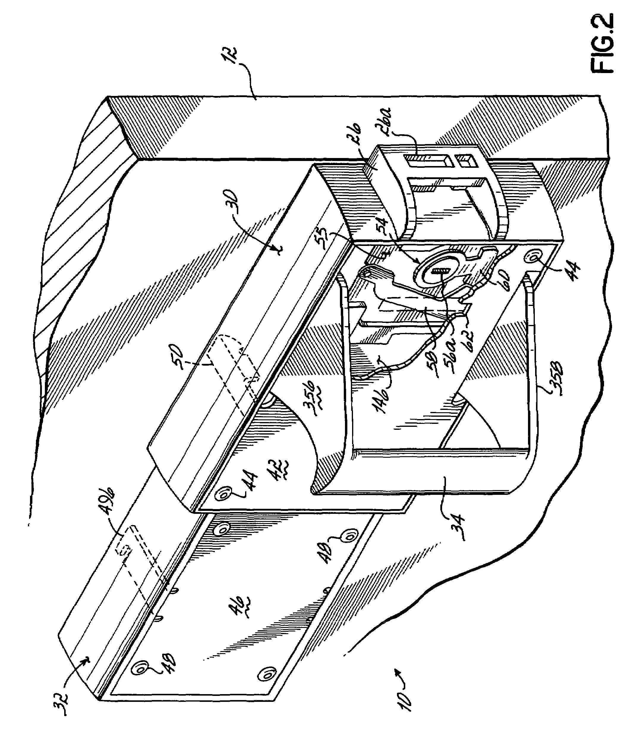
[0058]General Organization and Operation

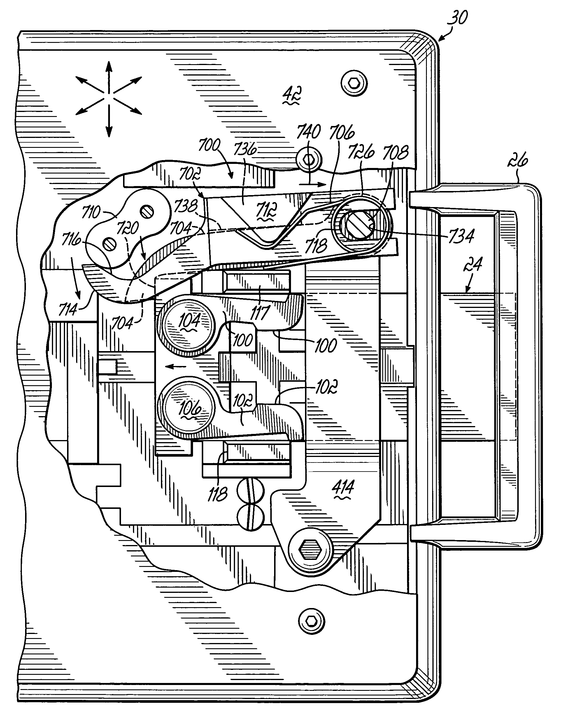
[0059]Referring generally to FIGS. 1 and 2, a dead bolt lock system 10 constructed in accordance with one preferred embodiment of the invention is shown attached to a door 12. Lock system 10 includes a primary lock 14, which may be a high security electro-mechanical lock, and a secondary lock 16, which may be high security or a lower security electric combination lock. A door handle or lever 18 disposed on the outside of door 12 is shown connected just below secondary lock 16. An optional access control 20 and an optional override 22 are further shown as possible accessories to lock system 10. Once locks 14 and 16 have been unlocked by a user, and access control 20 has been successfully actuated by the user, the door handle 18 may be rotated up or down to withdraw a dead bolt 24, in a manner to be described, to gain access to a secure area behind door 12. It will be appreciated that access control 20 may also be considered a “lock” for purpose...


PUM


Abstract

A dead bolt lock system having one or more security locks in conjunction with a dead bolt to provide various levels of security access to a door. An inertia assembly restrains movement of the dead bolt when a shock load is applied to the door, but allows the dead bolt to move when a shock load is not present. The inertia assembly includes an actuator weight and a bolt lock lever that can translate and rotate in response to the application of the shock load. In addition, the inertia assembly includes a return spring that biases the inertia assembly back into its original position for facilitating movement of the dead bolt after the application of the shock load.

Description

CROSS REFERENCE TO RELATED APPLICATIONS[0001]This application is a continuation-in-part of prior U.S. application Ser. No. 10 / 667,959, filed Sep. 22, 2003, now U.S. Pat. No. 7,007,524, which is a continuation-in-part of prior U.S. application Ser. No. 09 / 661,689 filed Sep. 14, 2000, now U.S. Pat. No. 6,622,534, which is a continuation of prior U.S. application Ser. No. 09 / 090,626, filed Jun. 4, 1998 (now abandoned), which is a continuation-in-part of prior U.S. application Ser. No. 08 / 797,438, filed Feb. 10, 1997 (now abandoned). The disclosure of each of these applications is hereby incorporated by reference herein in its entirety.FIELD OF THE INVENTION[0002]The present invention is directed generally to dead bolt locks and, more particularly, to dead bolt locks used on doors for accessing secure areas.BACKGROUND OF THE INVENTION[0003]The use of dead bolts for security purposes is widespread. One example of a high security dead bolt lock is shown in U.S. Pat. No. 5,257,519 to Mille...

Claims


Application Information

Patent Timeline
Patent Type & Authority Patents(United States)
IPC IPC(8): E05B65/10
CPCE05B47/0607E05B63/0017E05B63/0065E05B9/02G07C9/0069E05B15/004E05B17/2053E05B17/2088E05B17/2092E05B17/22E05B47/0002E05B63/20E05B65/1086E05B2047/0008E05B2047/0093E05B2063/207E05B13/005Y10S292/22Y10T70/5159Y10T70/577Y10T70/713Y10T292/0908Y10T70/7949
Inventor JASPER, THOMAS E.
Owner LOCKMASTERS
Why Eureka
Try Eureka