
Method for making mesh containers with a rail and mesh container formed therefrom

a technology of mesh containers and rails, applied in the field of containers, can solve the problems of inconvenient access to the contents of the lower container, lack of desirable characteristics of sheet metal,

Inactive Publication Date: 2008-09-30
DESIGN IDEAS LTD
View PDF71 Cites 37 Cited by
  • Summary
  • Abstract
  • Description
  • Claims
  • Application Information

AI Technical Summary

Benefits of technology

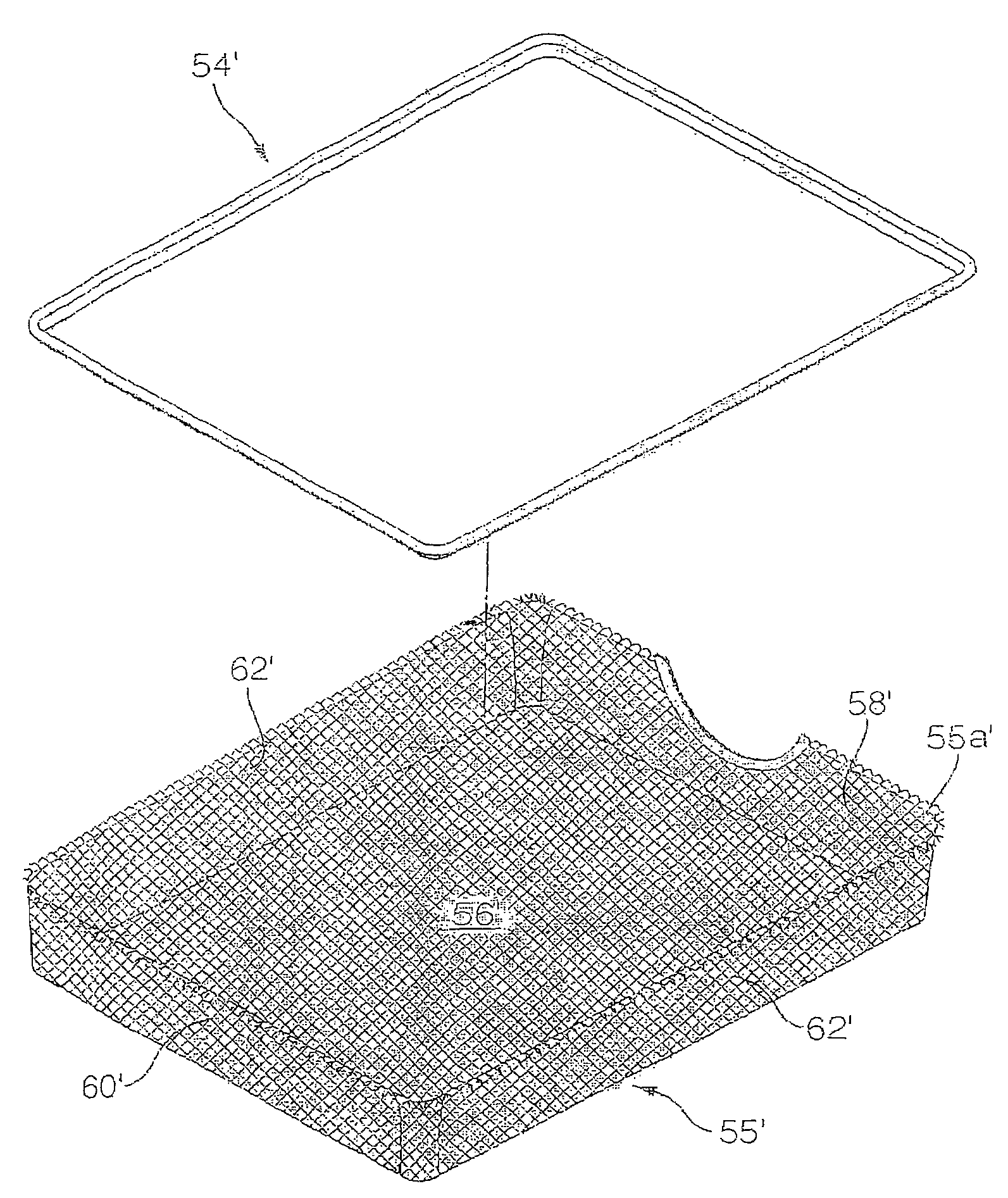
"The present invention is directed to a method of forming a container by bending an upper section of the sidewalls of a basket portion of metal mesh material outwardly and joining a rail to the basket portion. The rail is formed with an opening that receives the upper section of the sidewalls. The method includes steps of forming the basket portion with the sidewalls, bending the upper section of the sidewalls outwardly, inserting the basket portion into the opening of the rail, and compressing the rail to engage the basket portion. The invention also includes a container comprising a basket portion and first and second rails. The basket portion is formed of metal mesh material with closed or open corners between the sidewalls and the bottom wall. The rail has a L-shape and is joined to the basket portion and the sidewalls. The technical effects of the invention include improved stability and durability of the container, reduced labor and material costs, and improved efficiency in production."

Problems solved by technology

Sheet metal does not provide desirable characteristics such as drainage and ventilation.
The open corners of the basket and the slits between the sidewalls of the liner may allow small objects to fall out of the basket, which is undesirable.
Additionally, the containers do not move with respect to the frame so that the contents of the lower container are not easily accessible.

Method used


Image

  • Method for making mesh containers with a rail and mesh container formed therefrom
  • Method for making mesh containers with a rail and mesh container formed therefrom
  • Method for making mesh containers with a rail and mesh container formed therefrom

Examples


Embodiment Construction

OF THE PRESENT INVENTION

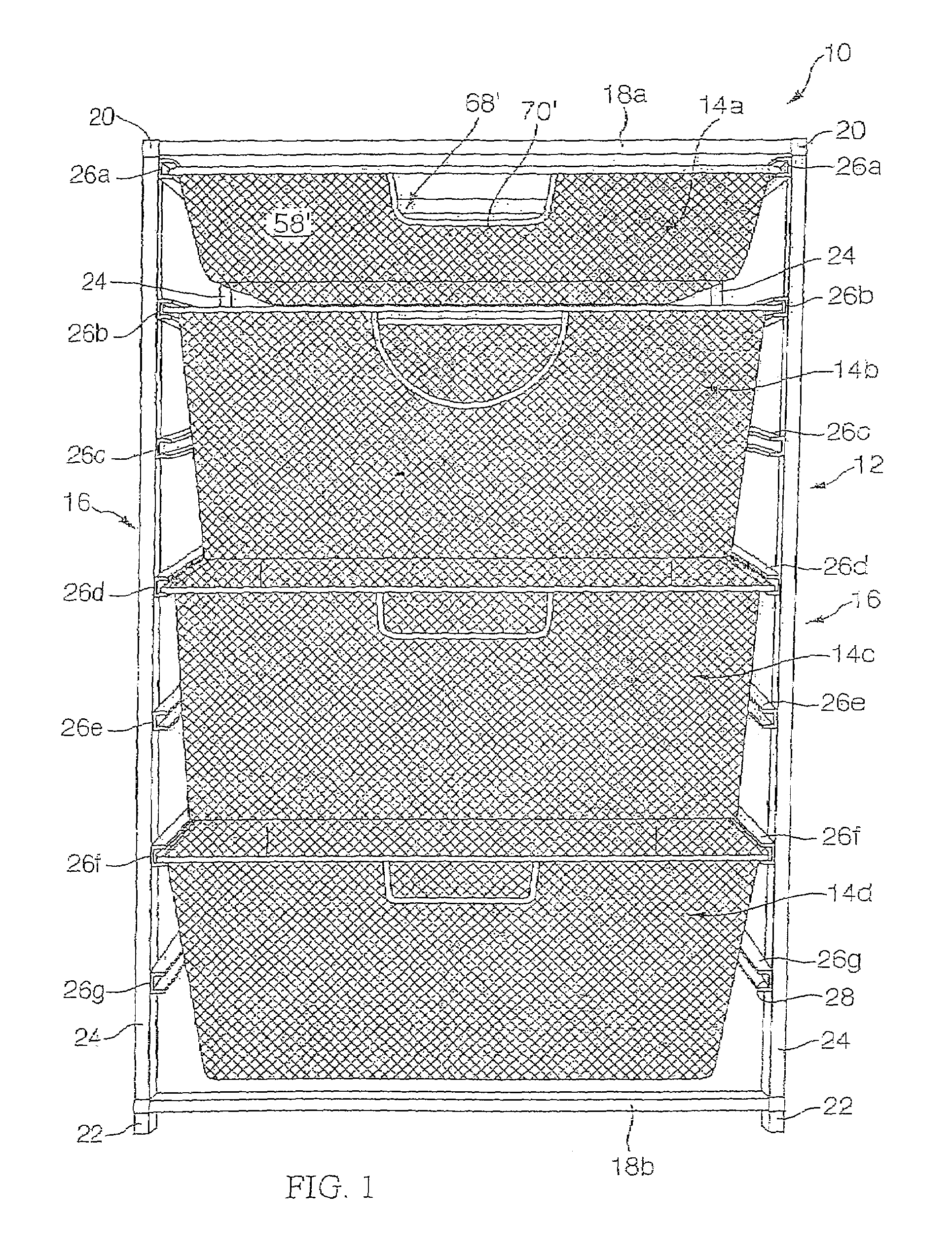
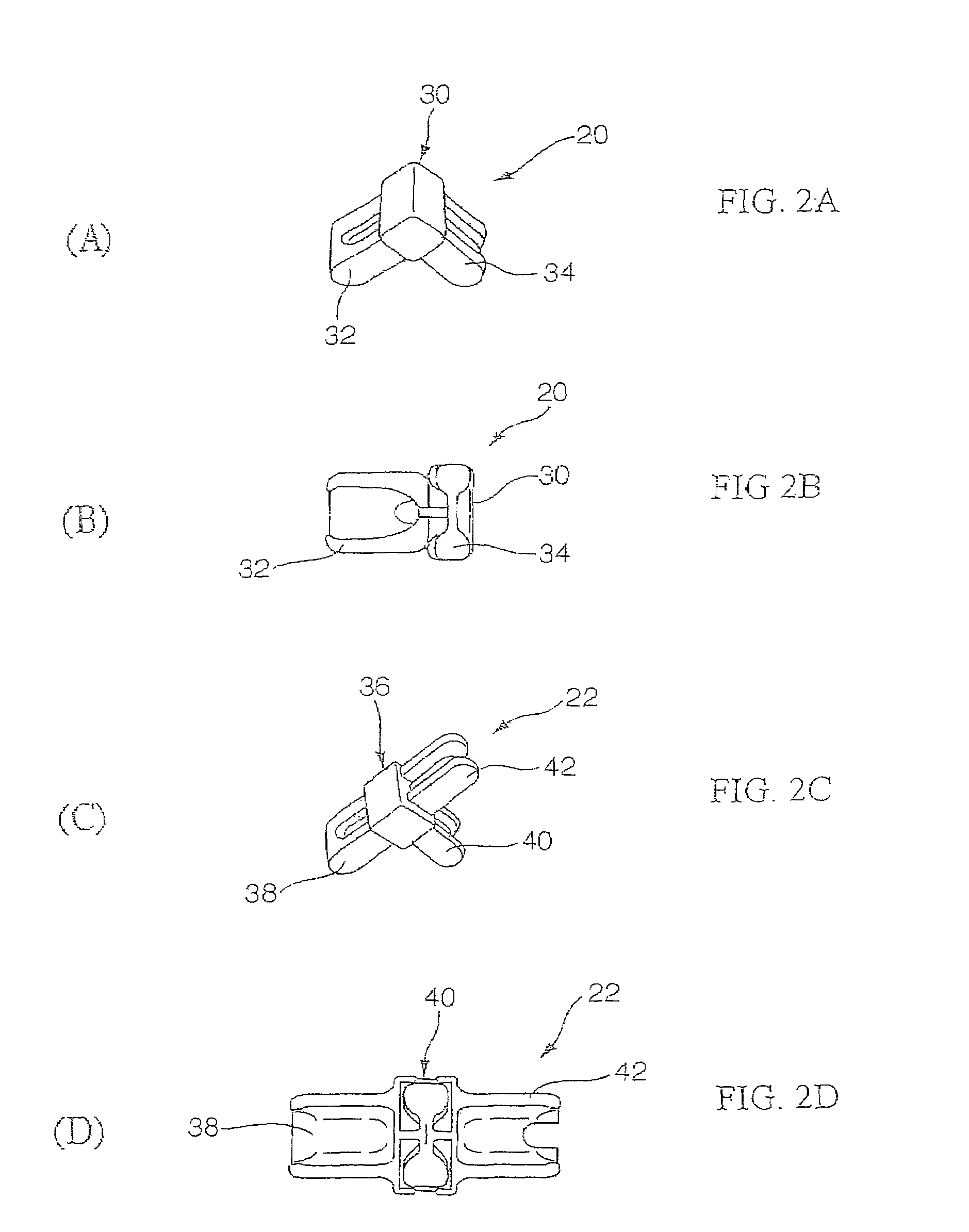
[0081]Referring to FIG. 1, a first example of drawer system 10 is shown. This drawer system 10 may be used to store a variety of housewares, such as kitchen items, clothing, accessories, sports equipment, shoes, bathroom supplies, tools, appliances, and the like. Additionally, system 10 can be used to store a variety of other items, for example food, office supplies, office equipment, file folders, papers / documents, bags, boxes, cans, bottles, etc.

[0082]Drawer system 10 includes frame 12 and a plurality of containers or drawers 14a-d. Drawer 14a is smaller than drawers 14b-c so drawer 14a can hold a smaller volume than other drawers 14b-d. Drawers 14a-d are movable with respect to frame 12 between a retracted position (shown in FIG. 1) and an extended position. In the retracted position, the contents of lower drawers 14b-d is difficult to access. In the extended position, the contents of the extended drawer are easily accessible; the extended drawer may be fu...


PUM

PropertyMeasurementUnit
angleaaaaaaaaaa
depthaaaaaaaaaa
sizesaaaaaaaaaa

Abstract

The present invention is directed to a method of forming a container comprising forming a basket portion of metal mesh material and a rail connected to the basket portion. The rail extends substantially outwardly from the outer surface of the basket portion and the rail extends continuously around the outer surface of the basket portion. In one example, the method includes forming the rail so that it does not contain or surround a free edge of the basket portion. In another example, the method includes forming the rail so that it includes an opening for containing or surrounding a free edge of the basket portion. The method may also include forming a lower rail. The present invention is also directed to a container formed by such method.

Description

CROSS-REFERENCE TO RELATED APPLICATIONS[0001]This application is a continuation-in-part of our prior pending application Ser. No. 10 / 972,308, filed Oct. 22, 2004 now U.S. Pat. No. 7,270,245, which is a continuation of Ser. No. 10 / 308,699, filed Dec. 3, 2002 now abandoned, which claims priority to the prior ROC (Taiwan) Patent Application No. 090220946, filed Dec. 3, 2001; ROC (Taiwan) Patent Application No. 091202306, filed Apr. 16, 2002; and ROC (Taiwan) Patent Application No. 091214244, filed Sep. 11, 2002. This application also claims priority to the prior ROC (Taiwan) Patent Application No. 093211506, filed Jul. 21, 2004; China Patent Application No. 200420084938.8, filed Jul. 28, 2004; ROC (Taiwan) Patent Application No. 093211507, filed Jul. 21, 2004; and China Patent Application No. 200420084546.1, filed Jul. 29, 2004. These applications are incorporated by reference herein in their entirety.BACKGROUND OF THE INVENTION[0002]1. Field of the Invention[0003]The present invention...

Claims


Application Information

Patent Timeline
Patent Type & Authority Patents(United States)
IPC IPC(8): B65D6/08B65D6/32B65D6/36B65D25/00A47B55/02A47B67/04B65D21/032B65D21/08
CPCA47B55/02A47B67/04B65D7/20B65D7/14Y10T29/49915
Inventor CHENG, HSI-MINGPOST, R. NEALHARDY, CHRISTOPHER
Owner DESIGN IDEAS LTD
Learn More