Brake system providing at least one enable signal to brake controllers and method of using same

a technology of enabling signal and brake controller, which is applied in the field of brake system, can solve the problems of difficult testing and maintenance of software to this level of reliability, uncontrolled aircraft braking, and uncontrollable braking at critical times such as takeoff, and achieve the effect of preventing uncontrolled aircraft braking

Active Publication Date: 2008-10-14
HONEYWELL INT INC
View PDF19 Cites 6 Cited by
  • Summary
  • Abstract
  • Description
  • Claims
  • Application Information

AI Technical Summary

Benefits of technology

[0008]Another aspect of the invention comprises a method of preventing uncommanded aircraft braking when an aircraft is on the ground that includes the steps of providing a software module for producing a direct enable signal on a bus when braking is authorized, and connecting a first controller, a second controller and a brake control system (BCS) to the bus. The first controller and second controller are connected to the BCS, and a first driver is connected to the first controller and second driver is connected to the second controller. The first controller is connected to the second controller. An indirect enable signal is sent from the first controller to the second controller when the first controller receives a direct enable signal from the bus and a brake command from the BCS. A control signal is sent to the first driver when the first controller receives a direct enable signal from the bus and an indirect enable signal from the second controller and a brake command from the BCS.

Problems solved by technology

Uncommanded braking may also occur immediately after take off to stop the landing gear wheels from rotating before the landing gear is retracted.
Because uncommanded braking is controlled by a computer, there is a possibility that it will occur as the result of a software bug or malfunction.
Such uncommanded braking during takeoff could be disastrous, and thus braking systems must be designed so that uncommanded braking at critical times such as takeoff is extremely improbable.
However, testing and maintaining software to this level of reliability is difficult and very expensive.
However, wiring for the redundant circuit has to be run from brake pedals in the cockpit to a driver in or near the aircraft wheel well.
This increases the weight and cost of the brake system and adds maintenance costs as well.

Method used


Image

  • Brake system providing at least one enable signal to brake controllers and method of using same
  • Brake system providing at least one enable signal to brake controllers and method of using same
  • Brake system providing at least one enable signal to brake controllers and method of using same

Examples


Embodiment Construction

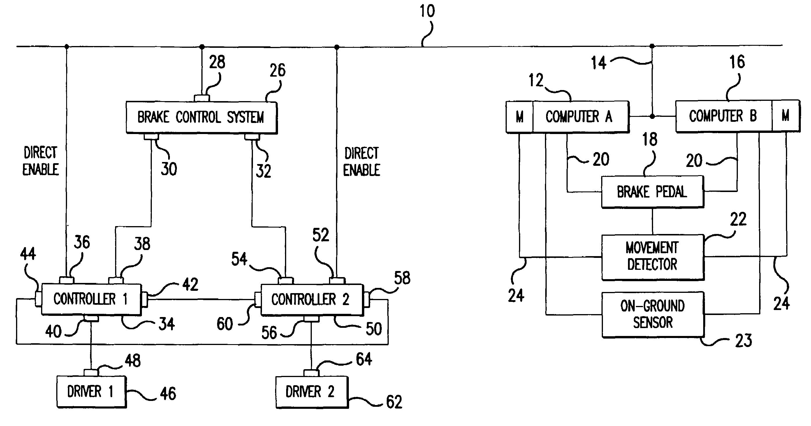
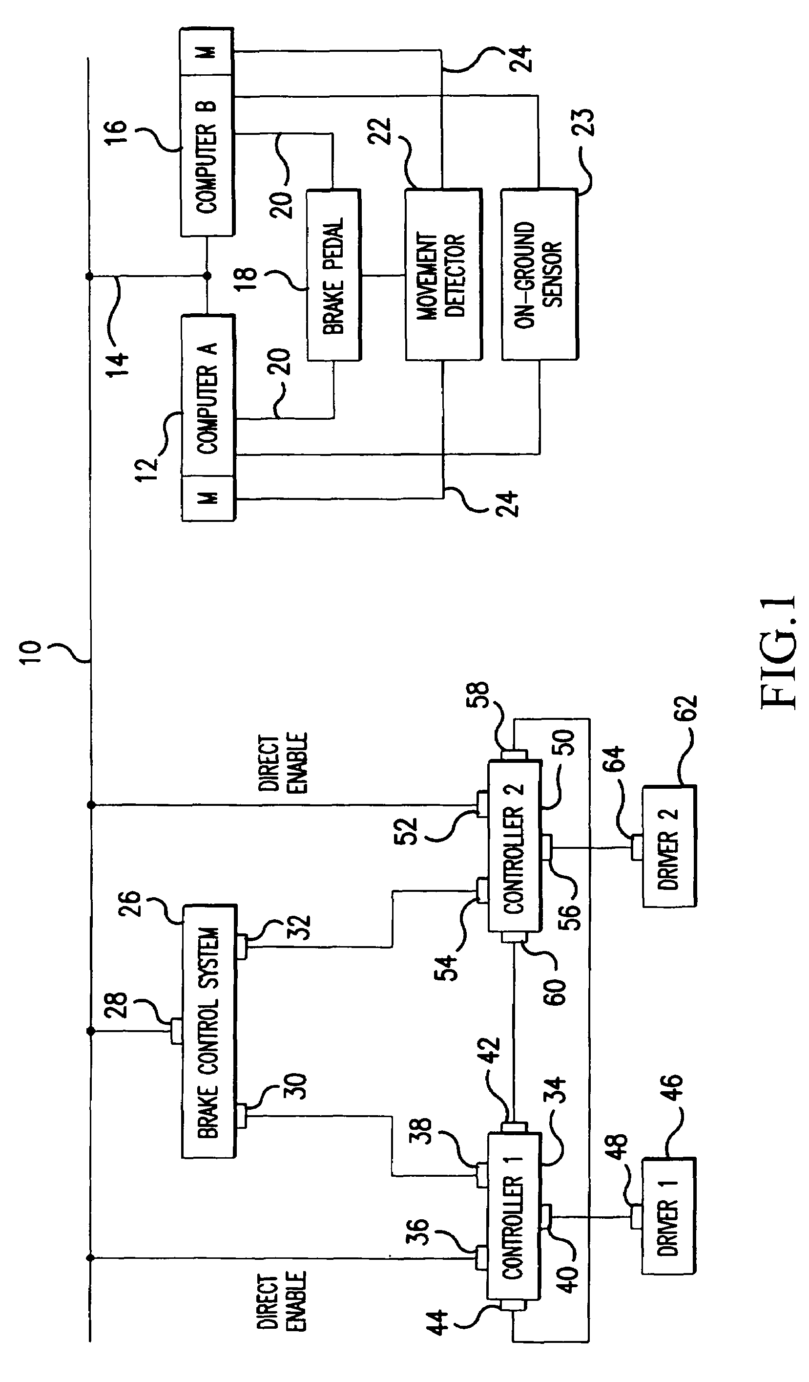
[0014]Referring now to the drawings, wherein the showings are for purposes of illustrating preferred embodiments of the invention only and not for the purpose of limiting same, FIG. 1 illustrates a braking system that includes a bus 10 and a first computer 12 connected to bus 10 by a line 14 and a second, redundant computer 16 connected to bus 10 by line 14. Each of the first and second computers 12, 16, which may constitute the main cockpit control computers of an aircraft, for example, run a software module M which senses the position of a brake pedal brake pedal 18. Brake pedal 18 is connected to first and second computers 12, 16 by first lines 20 that carry braking signals to computers 12, 16. Brake pedal 18 is also connected to a movement detector 22 which sends a signal over second lines 24 to the software modules M of first and second computers 12, 16 each time movement of brake pedal 18 is detected. An on-ground sensor 23, such as a sensor for determining when the weight of ...


PUM


Abstract

A braking system includes a brake control system (BCS) (26) having a first output (30) and a second output (32), a first controller (34) having a brake command input (38) connected to the BCS first output (30), a direct enable input (36), an indirect enable input (44), a driver output (40) and an indirect enable output (42), a second controller (50) having a brake command input (54) connected to the BCS second output (32), a direct enable input (52), an indirect enable input (60), a driver output (56) and an indirect enable output (58). The first controller (34) produces an indirect enable signal on the first controller indirect enable output (42) when a direct enable signal is received at the first controller direct enable input (36) and a brake command signal is received at the brake command input (54), and produces a driver actuation signal on the first controller driver output (40) when a direct enable signal is present on the first controller direct enable input (52) and an indirect enable signal is present on the first controller indirect enable input (44) and a brake command is received on the first controller brake command input (38).

Description

FIELD OF THE INVENTION[0001]The present invention is directed to a brake system that uses redundant control signals and a method of controlling same, and, more specifically, toward a brake system that provides at least one enable signal to a brake controller to establish when braking is authorized and a method of using such a system.BACKGROUND OF THE INVENTION[0002]Aircraft brake systems can generally carry out both commanded and uncommanded braking. Commanded braking occurs when a pilot depresses a brake pedal or in some other manner produces a signal to initiate braking. Uncommanded braking occurs when an aircraft computer or aircraft brake control system (BCS) actuates an aircraft's brakes without pilot input. Uncommanded braking is used, for example, to test an aircraft's brakes prior to landing to ensure they are in working order. Uncommanded braking may also occur immediately after take off to stop the landing gear wheels from rotating before the landing gear is retracted.[000...

Claims


Application Information

Patent Timeline
Patent Type & Authority Patents(United States)
IPC IPC(8): B60T7/12
CPCB60T8/1703
Inventor KOLBERG, DAVID A.
Owner HONEYWELL INT INC
Why Eureka
Try Eureka