Agricultural tractor with movable step

a technology of agricultural tractor and movable step, which is applied in the direction of steering control, loading vehicle superstructure, building scaffold, etc., to achieve the effect of safety and protection

Active Publication Date: 2008-10-21
MACDON INDS
View PDF9 Cites 59 Cited by
  • Summary
  • Abstract
  • Description
  • Claims
  • Application Information

AI Technical Summary

Benefits of technology

[0035]The space underneath the platforms is thus a suitable location to mount the valve blocks, toolbox, fuse panel, A / C breather, and batteries and at the same time keeping them well protected. The challenge lay in giving these components and the engine bay the safe serviceability and protection that is needed while not requiring the operator to fumble with guards, panels, pins and fold out ladders, etc.
[0036]The thought was to take the right and left side platform structures that provide safe, secure ingress and egress from the operator station at the cab end of the machine, and cause them be moved to the engine end of the machine. This only exposes the previously mentioned components underneath the platform for easy service but also provides the same safe, firm footing for serviceable items higher up at the engine and for any maintenance items under the hood of the tractor while it is open.

Problems solved by technology

Today's self propelled agricultural equipment is a complex mix of leading edge, state of the art designs, and proven engineering methods.

Method used


Image

  • Agricultural tractor with movable step
  • Agricultural tractor with movable step
  • Agricultural tractor with movable step

Examples


Embodiment Construction

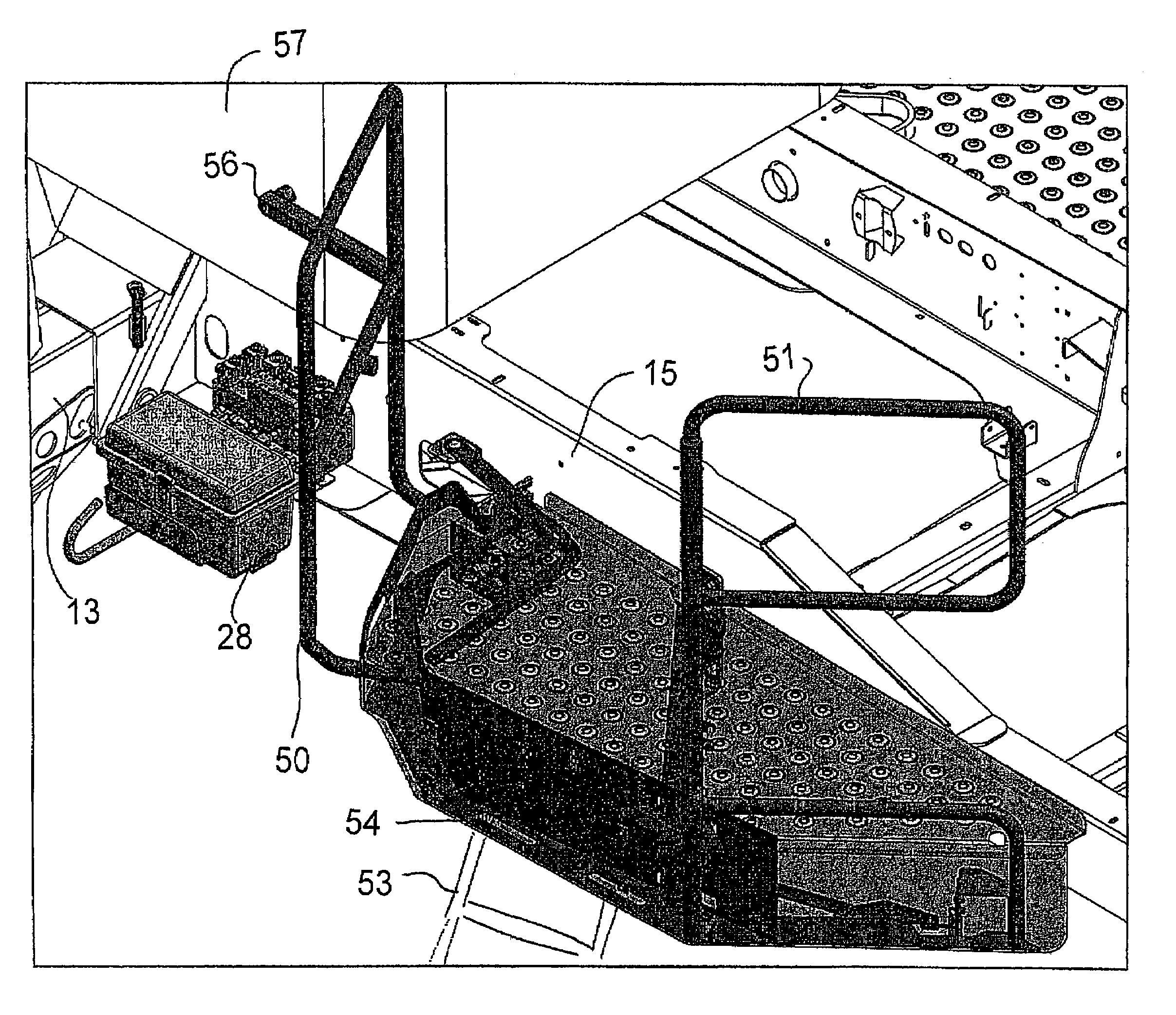
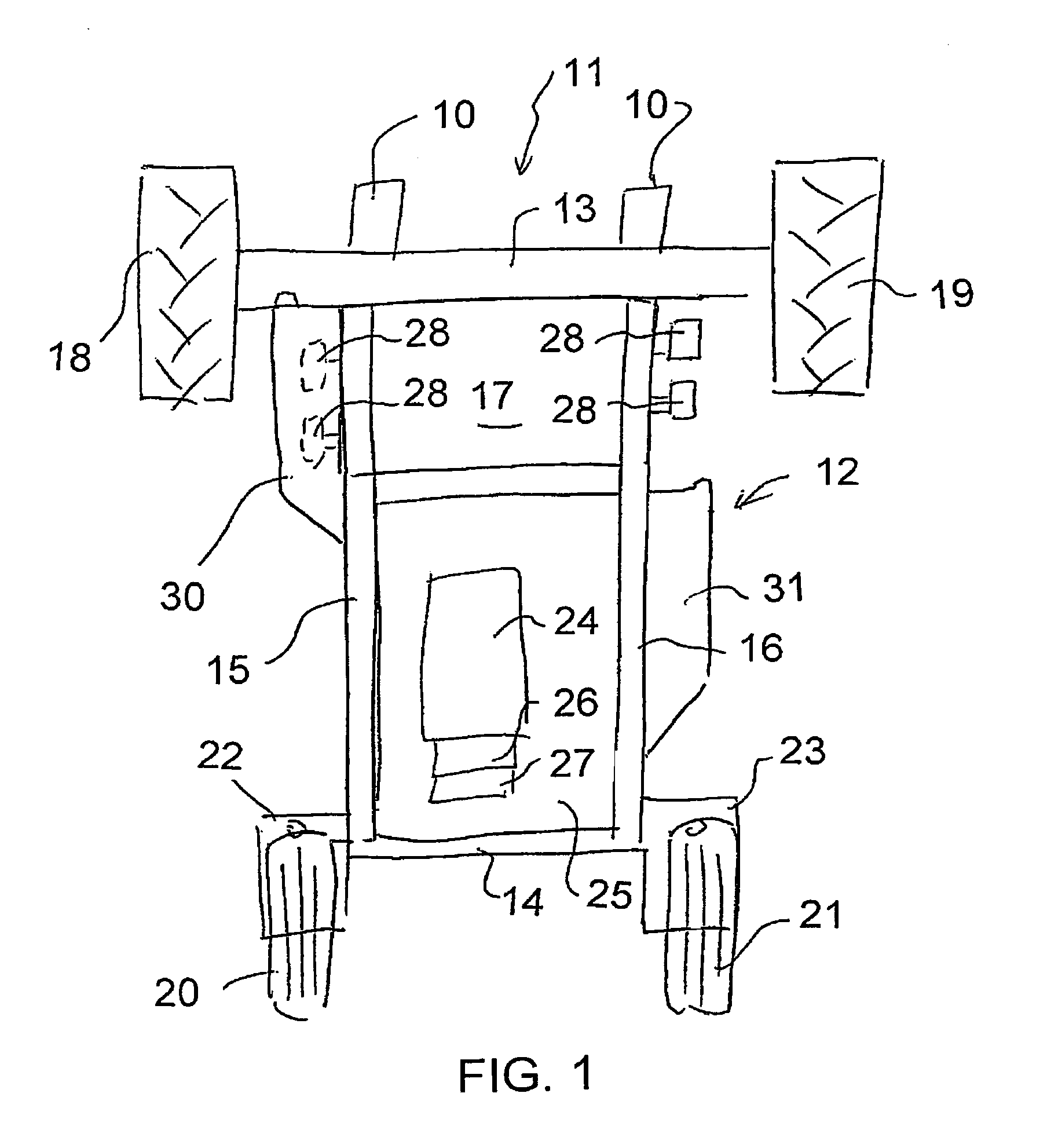
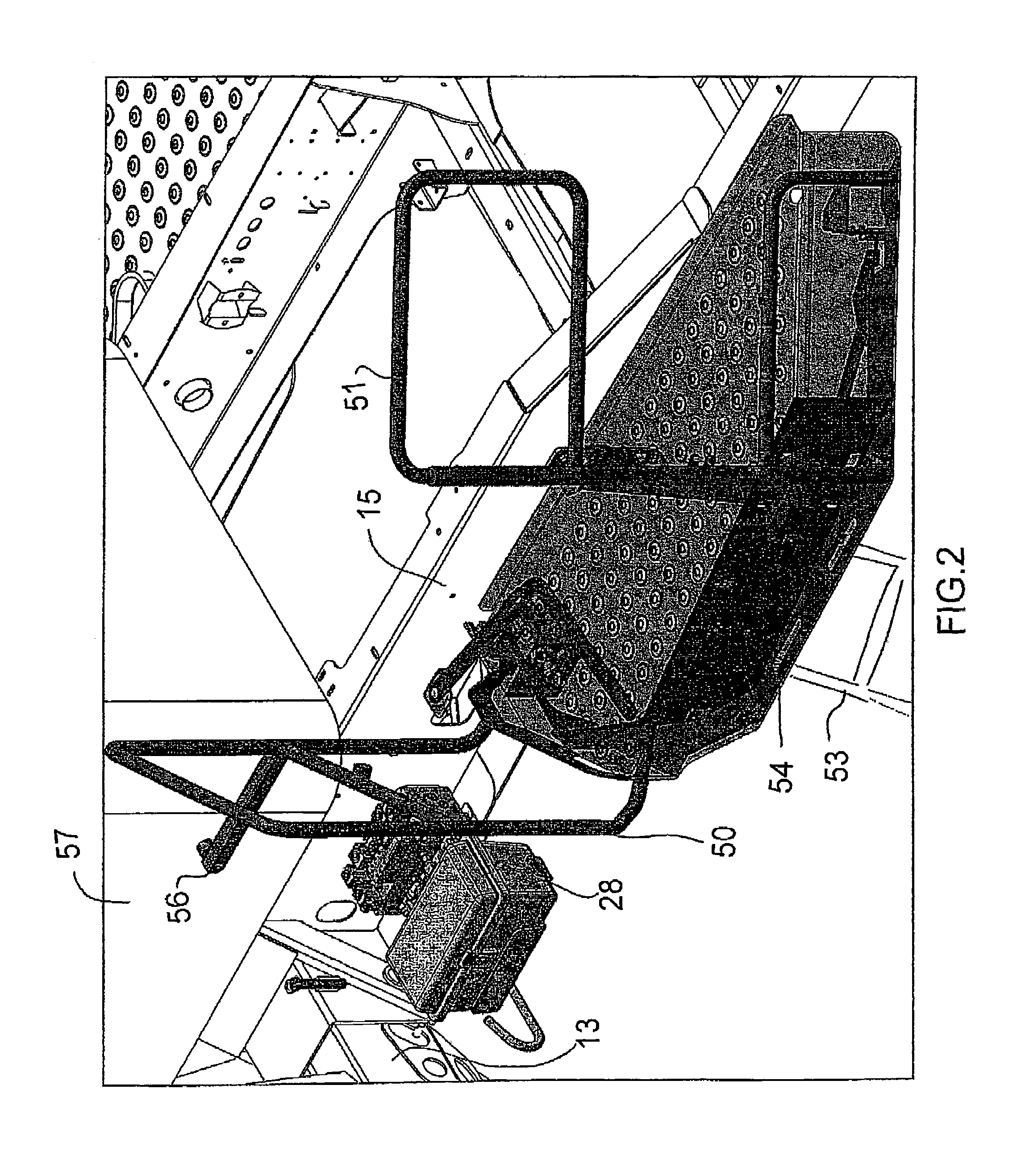
[0048]In FIG. 1 is shown schematically a tractor of the type commonly used for providing a self-propelled swather. The swather generally includes a header which is not illustrated but is mounted on arms 10 at the front of the tractor generally indicated at 11. The tractor comprises a frame generally indicated at 12 defined by cross members 13 and 14 at the front and rear of the frame together with longitudinal side rails 15 and 16.

[0049]In this type of tractor there is provided a cab 17 located at the front over the front cross member so that the operator can see over the header attached to the arms 10 for forward operation of the tractor. The frame is mounted on front ground wheels 18 and 19 and on rear ground wheels 20 and 21. Commonly the front ground wheels 18 and 19 are the driven wheels which are hydraulically driven. The rear wheels 20 and 21 are commonly castor wheels mounted on castors schematically indicated at 22 and 23 so that the control of the speed and direction of th...


PUM


Abstract

A tractor has a frame defined by two side rails extending longitudinally carried on ground wheels with a cab on the frame at one end and an engine compartment at the other end. The cab has doors on each side and there are provided two operator platforms each attached to the frame at a respective side with suitable ladder, guard rails and surface by which the operator can climb to the cab. Each operator platform is mounted for movement longitudinally of the frame on levers allowing movement along the side of the frame from the cab entry position to an engine service position. The platform can cover operator serviceable parts which in the cab position which are exposed when the platform is moved to the engine service position.

Description

[0001]This application claims the priority under 35 U.S.C. 119 of Provisional Application No. 60 / 698,972 filed Jul. 14, 2005[0002]This invention relates to an agricultural tractor with a movable step which can be located in a first position alongside a cab of the tractor and can be moved longitudinally of the tractor to a second position alongside an engine of the tractor.BACKGROUND OF THE INVENTION[0003]Today's self propelled agricultural equipment is a complex mix of leading edge, state of the art designs, and proven engineering methods. Self-propelled windrowing traction units which MacDon builds are no exception. They must provide maximum flexibility in a wide range of crops with a wide range of header options. To accommodate and provide the necessary resources for an ever increasing line of headers and their options, there must be a multitude of windrower system functions all packed in to the framework of the windrower. At the same time, all these systems; electrical, HVAC and ...

Claims


Application Information

Patent Timeline
Patent Type & Authority Patents(United States)
IPC IPC(8): B60R3/02
CPCB60R3/02
Inventor SCHULZ, HENRY JEROME
Owner MACDON INDS
Why Eureka
Try Eureka