Method and device for thermal ablative pyrolysis of biomass

a technology of biomass and ablative pyrolysis, which is applied in the direction of hydrocarbon preparation, liquid hydrocarbon mixture production, drying peat, etc., can solve the problems of reducing process efficiency, high energy consumption of fine particles, and complex construction of the reactor, so as to reduce the temperature of the heating element, reduce the cost of equipment, and reduce the effect of energy consumption

Inactive Publication Date: 2008-10-21
PYTEC THERMOCHEM ANLAGEN
View PDF4 Cites 60 Cited by
  • Summary
  • Abstract
  • Description
  • Claims
  • Application Information

AI Technical Summary

Benefits of technology

[0007]The heating element is designed as a plane or arched panel, which is optionally composed of individual segments. The heating element may thus be adapted in a simple manner to the size of the installation. The design as an arched panel, for a given diameter, permits the enlargement of the available heating surface. The withdrawal of pyrolysis products is moreover simplified if an arched heating element is used. The simple, plane panel, on the other hand, is a reasonably priced and easily performed solution for the heating element.
[0029]The plant according to the invention comprises a heating element made of a heat-resistant material, preferably metal, ceramics or a material comprising metallic and ceramic components, provided with a drive means. The drive means has the effect that the heating element rotates in the operating state. The heating element has a working surface against which the biomass to be pyrolysed is pressed in the operating state. On the side opposite the heating element, the heating surface, means for direct or indirect heating are provided. Preferably, open coal burners are provided the combustion gas of which is recovered from pyrolytically produced char. This form of direct heating offers a high degree of efficiency and is moreover economical, as in this manner the energy content of the char is well utilised immediately without complex processing or long transport.

Problems solved by technology

The installations described there have in common that the construction of the reactors and the processing of the pyrolysis products are relatively complicated.
The production of such fine particles is highly energy consuming and reduces the efficiency of the process.

Method used


Image

  • Method and device for thermal ablative pyrolysis of biomass
  • Method and device for thermal ablative pyrolysis of biomass
  • Method and device for thermal ablative pyrolysis of biomass

Examples


Embodiment Construction

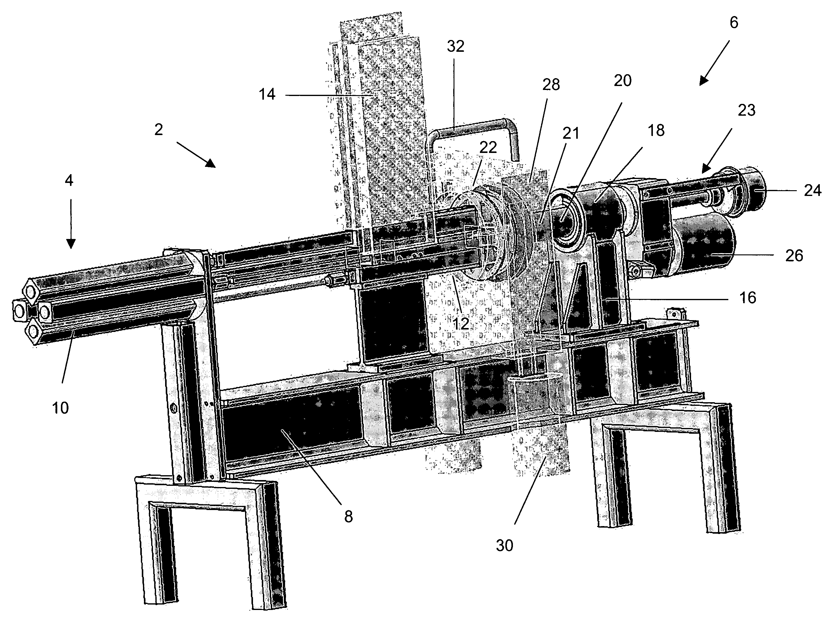
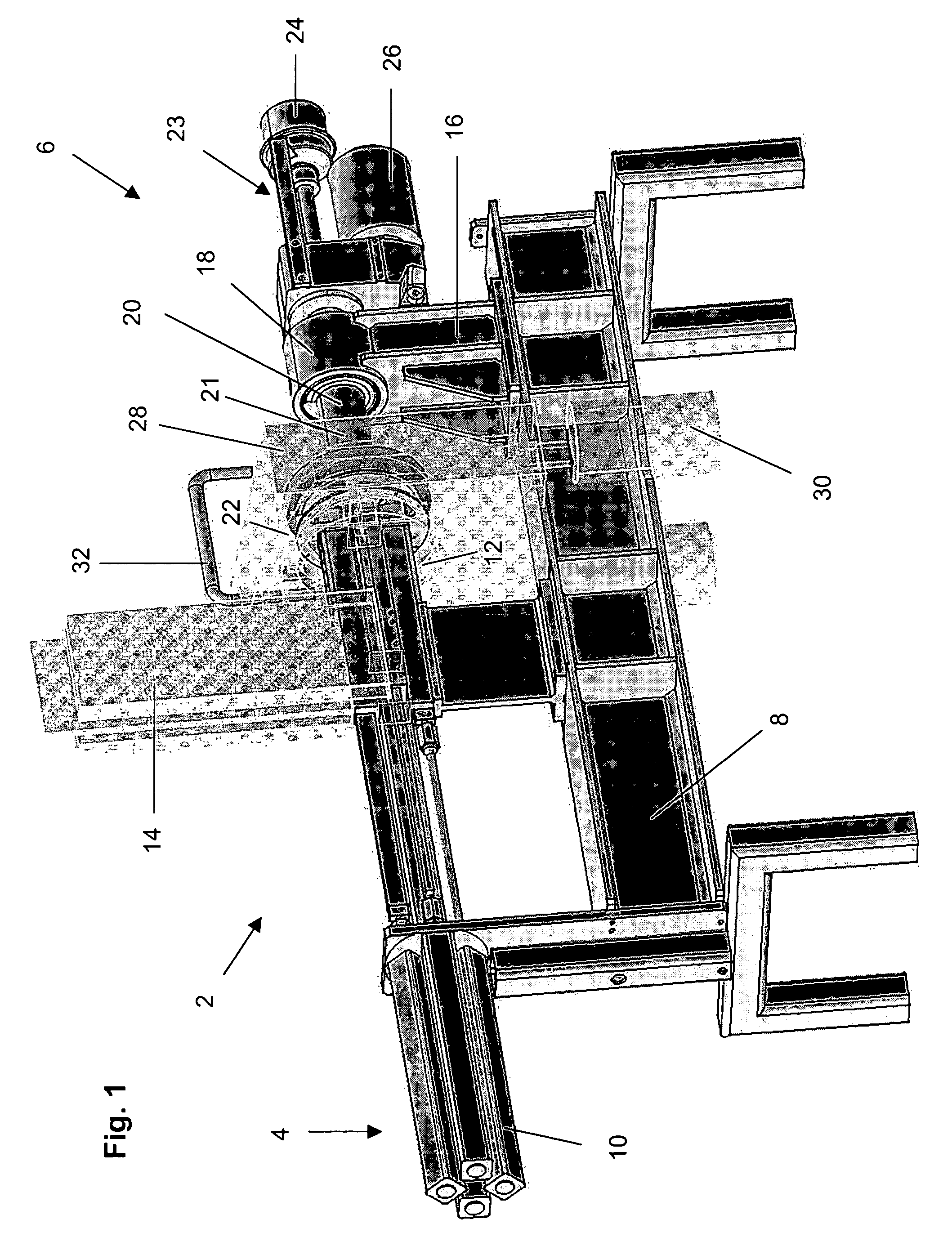
[0044]FIG. 1 shows an apparatus 2 for pyrolysis, wherein the material feed 4 and the pyrolysis station 6 are provided on a joint beam 8. The material feed 4 comprises a component 10 for generating the required contact pressure on the pyrolysis station 6. Here, the component 10 generates the pressure by means of hydraulics (hydraulic component 10). Furthermore, the material feed 4 comprises feed means 12 for the raw material to be pyrolysed. Four parallel feed means 12 are provided, each of which is acted upon by its own, associated hydraulic component 10 via hydraulic pistons (not shown in detail) with the required pressure of between about 5 bars and about 200 bars. At the same time the hydraulic component brings about the feeding of the raw material to the pyrolysis station 6.

[0045]The raw material is fed into the feed means 12 via feeding hoppers 14. One hopper 14 each is assigned to each feed means 12. The hoppers 14 may in each case be charged manually or automatically. In prin...


PUM

PropertyMeasurementUnit
pressureaaaaaaaaaa
pressureaaaaaaaaaa
pressureaaaaaaaaaa

Abstract

A method for the pyrolosis of biomass with the aid of a heating element and a feed for guiding the biomass. During pyrolysis, the heating element and the biomass are pressed against each other at a pressure of 5 bars-80 bars. A device for pyrolysing biomasses, comprises a material supply and a pyrolysing station. The material supply comprises elements for generating a pressure of between 5 bars and 200 bars, pressing the raw material which is to be pyrolysed against the pyrolysing station. The pyrolysing station comprises a heating element which is heated to a temperature of between 300° C. and 1000° C. in an operational state.

Description

BACKGROUND OF THE INVENTION[0001]The invention relates to a process for the ablative pyrolysis of biomass by means of a heating element and by means for feeding the biomass as well as to a plant therefor and to a fuel produced according to the invention.[0002]Pyrolysis denotes a process, wherein organic material is decomposed, mostly in the absence of oxygen, into gaseous, liquid and solid decomposition products at temperatures of up to approximately 600° C. The object is to maximise the liquid decomposition products which may be used in a variety of manners as a pyrolysate having a high energy content. Flash-pyrolysis is particularly suitable for the technical conversion. The organic material to be decomposed is heated in the shortest possible time to temperatures of about 450° C. to 500° C. and the pyrolysis products formed are for the most part condensed into a pyrolysate.[0003]Processes operating according to the principle of flash-pyrolysis use e.g. sand bed reactors, wherein f...

Claims


Application Information

Patent Timeline
Patent Type & Authority Patents(United States)
IPC IPC(8): B01J8/00C10B47/12C10B53/02C10G1/02
CPCC10B47/12C10B53/02C10G1/02C10G2300/1018C10G2300/1003C10G2300/1014Y02E50/14Y02P20/145Y02P20/143Y02P30/20Y02E50/10
Inventor MEIER, DIETRICHKLAUBERT, HANNESSCHOLL, STEFAN
Owner PYTEC THERMOCHEM ANLAGEN
Why Eureka
Try Eureka