Perforation gun with integral debris trap apparatus and method of use

a technology of debris trap and perforation gun, which is applied in the field of perforation guns, can solve the problems of preventing reduced shaped charge performance, and achieve the effects of reducing or eliminating damage, preventing reduced shaped charge performance, and less resistan

a technology of debris trap and perforation gun, which is applied in the field of perforation guns, can solve the problems of preventing reduced shaped charge performance, and achieve the effects of reducing or eliminating damage, preventing reduced shaped charge performance, and less resistan

US7441601B2Inactive Publication Date: 2008-10-28WELLS FARGO BANK NAT ASSOC +1

Image

  • Perforation gun with integral debris trap apparatus and method of use
  • Perforation gun with integral debris trap apparatus and method of use
  • Perforation gun with integral debris trap apparatus and method of use

Examples


Embodiment Construction

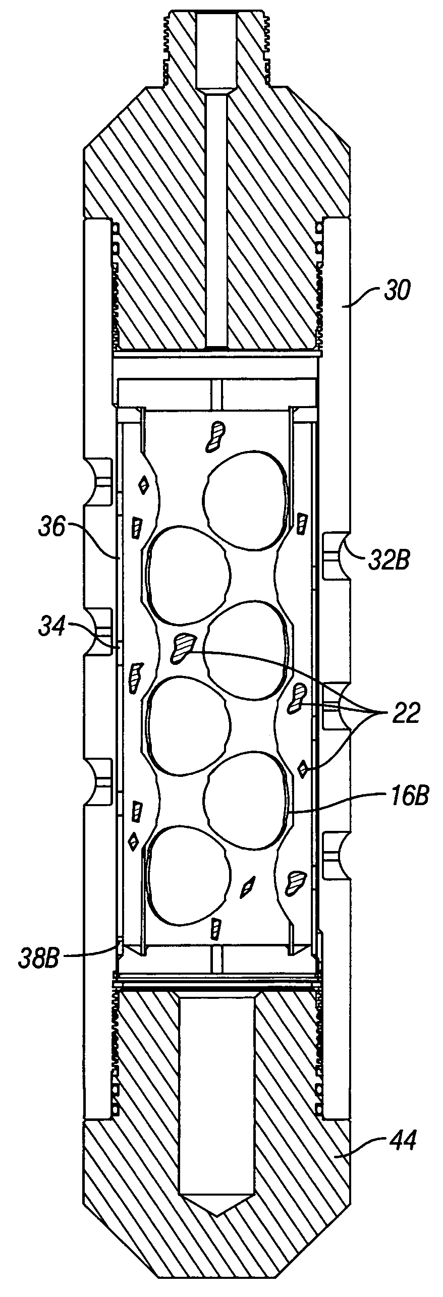
[0025]The present invention involves an improved debris trapping perforation gun and the unique charge carrier or inner sleeve it incorporates. The invention produces superior debris trapping results because the pre-drilled holes in the charge carrier or inner sleeve, as appropriate, limits or eliminates deformations caused by the explosive charges which allows the charge carrier or inner sleeve to shift with more ease and success.

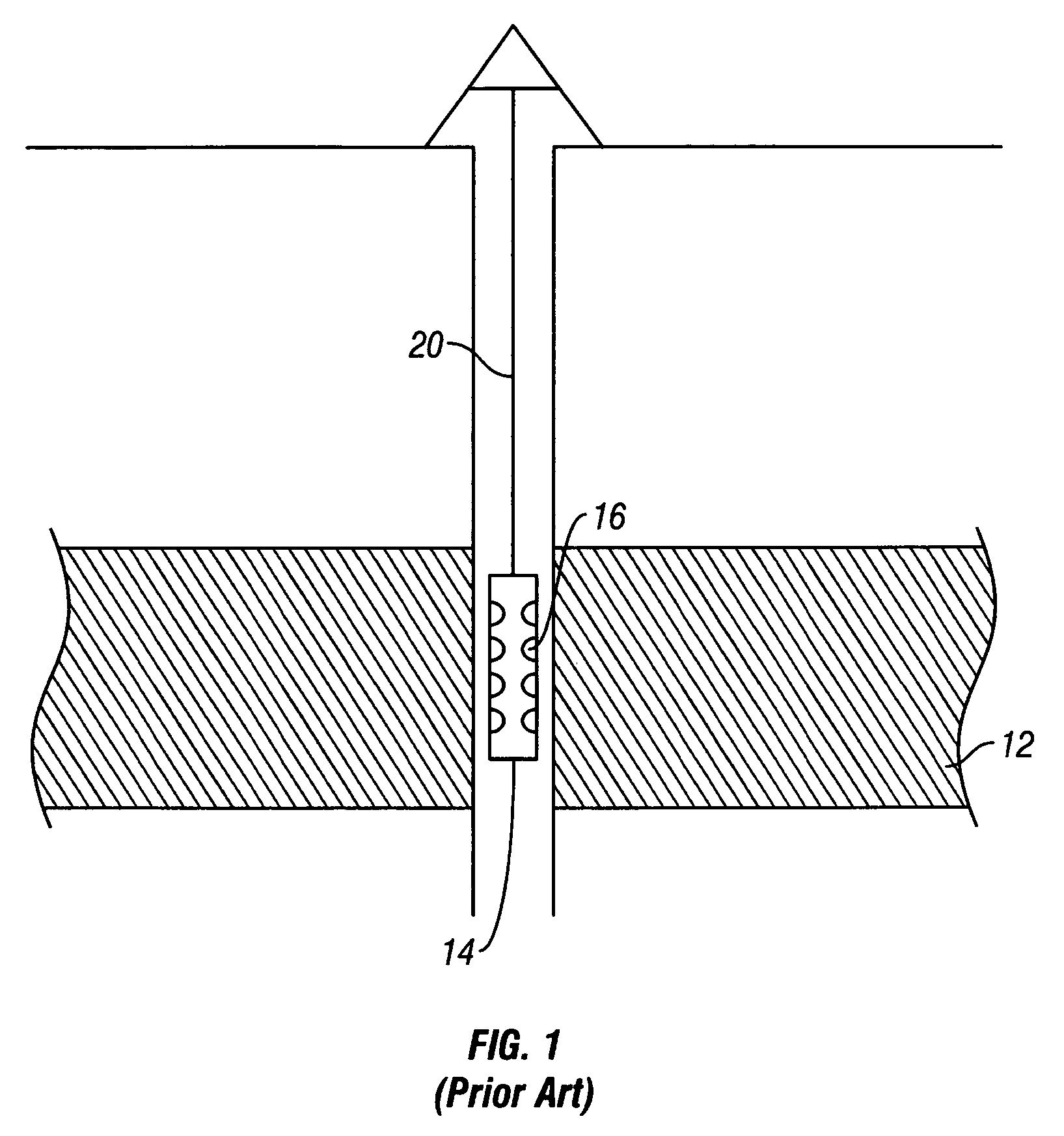
[0026]Referring initially to FIG. 1, the reference numeral 14 refers in general to a perforation gun (of which the present invention is one type), which has been lowered into a well bore to the depth of a hydrocarbon bearing formation 12.

[0027]Even though FIG. I shows a vertical well, one skilled in the art knows that the perforation gun of the present invention is equally well-suited for use in wells having other geometries such as deviated wells, inclined wells, or horizontal wells. Accordingly, use of directional terms such as above, below, up, down, up...


PUM


Abstract

An improved perforation gun includes an outer gun barrel, which is used in conjunction with an inner movable charge carrier or an inner movable sleeve to trap virtually all of the debris created by the firing of the perforation gun. The charge carrier has a plurality of explosive charges initially aligned with complementary, pre-existing holes in the wall of the charge carrier, which are initially aligned with complementary, pre-existing scalloped sections of the outer gun barrel.

Description

CROSS-REFERENCE TO RELATED APPLICATION[0001]This application claims the benefit of and priority to a U.S. Provisional Patent Application No. 60 / 681,553 filed May 16, 2005, the technical disclosure of which is hereby incorporated herein by reference.BACKGROUND OF THE INVENTION[0002]1. Technical Field of the Invention[0003]The present invention relates generally to perforation guns that are used in the oil and gas industry to explosively perforate well casing and underground hydrocarbon bearing formations, and more particularly to an improved method and an improved apparatus for explosively perforating a well casing and its surrounding underground hydrocarbon bearing formation while limiting the amount of explosion debris in the well bore and hydrocarbon bearing formation following perforation.[0004]2. Description of the Related Art[0005]During the completion of an oil and / or gas well, it is common to perforate the hydrocarbon containing formation with explosive charges to allow inflo...

Claims


Application Information

Patent Timeline
28 Oct 2008
Publication
US7441601B2
IPC
E21B43/116
CPC
E21B43/117; E21B43/119
Inventors
GEORGE, KEVIN; CLARK, NATHAN