Oxygen sensor regeneration

a technology of oxygen sensor and oxygen sensor, which is applied in the direction of machines/engines, electrical control, instruments, etc., can solve the problems of engine damage and negative impact on exhaust emissions, and contamination of oxygen sensor, so as to eliminate or reduce the damage to the sensor

Active Publication Date: 2014-02-20
ROBERT BOSCH CORP +1
View PDF18 Cites 20 Cited by
  • Summary
  • Abstract
  • Description
  • Claims
  • Application Information

AI Technical Summary

Benefits of technology

[0005]In one embodiment, the invention provides methods and systems for heating an O2 sensor to a temperature where contaminants are burned off, but damage to the sensor is eliminated or reduced. In particular, the temperature that the sensor is heated to is based on an internal resistance of the sensor at the time the heating is carried out. Heating of the sensor is often referred to as an “increased temperature cycle” or a “cleaning cycle,” and the overall process of removing contamination is referred to as “sensor regeneration.” Heating occurs as a result of applying a pulse-width-modulated (“PWM”) voltage signal to the sensor (via a heating element located in the sensor). The PWM signal is created based on an algorithm or calculation performed in a controller (such as a microprocessor). The algorithm uses a software-chosen internal resistance value of the O2 sensor (i.e., the Nernst cell included in the sensor) associated with a desired temperature (for example, from a look-up table).

Problems solved by technology

This situation is referred to as a rich mixture or rich condition and has a negative impact on exhaust emissions.
When an engine burns lean, engine performance may decrease and, in some cases, may cause engine damage and have a negative impact on exhaust emissions.
Over time, contaminants (such as soot) build up on O2 sensors.
If these contaminants are not removed, the sensors will not operate properly.
However, overheating the sensor to burn off contaminants can damage the sensor.

Method used


Image

  • Oxygen sensor regeneration
  • Oxygen sensor regeneration
  • Oxygen sensor regeneration

Examples


Embodiment Construction

[0015]Before any embodiments of the invention are explained in detail, it is to be understood that the invention is not limited in its application to the details of construction and the arrangement of components set forth in the following description or illustrated in the following drawings. The invention is capable of other embodiments and of being practiced or of being carried out in various ways

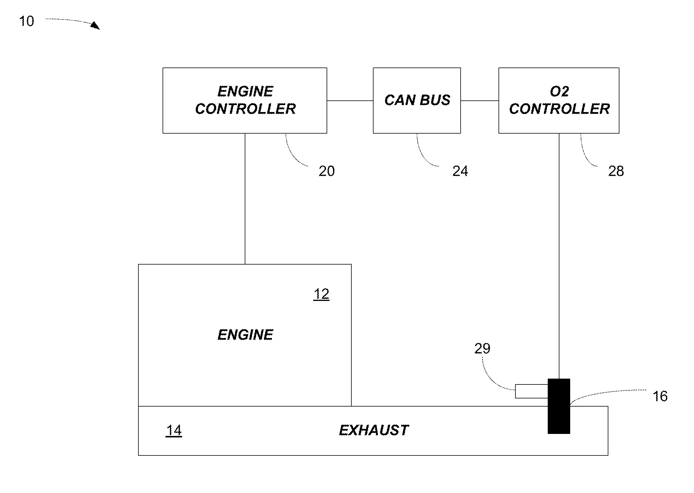
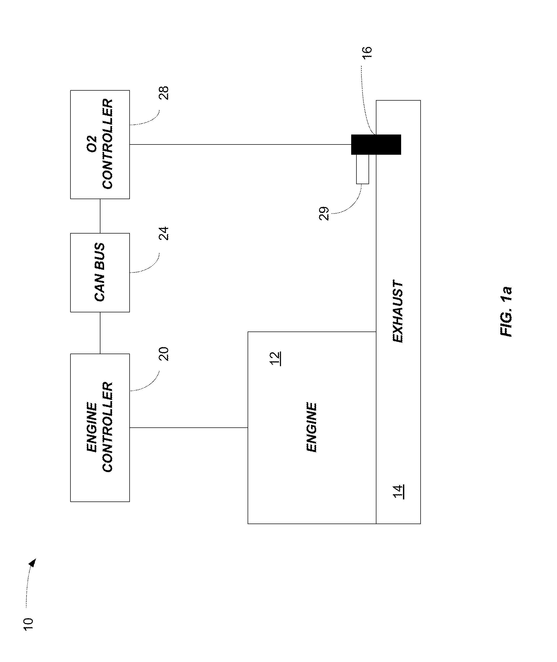
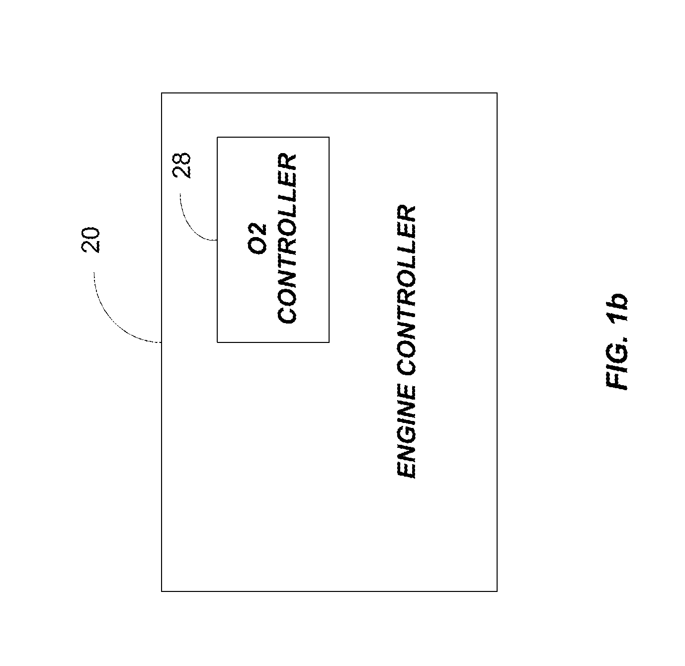
[0016]FIG. 1a illustrates a system 10 having an engine 12, an exhaust system 14, and an O2 sensor 16 (including a heater) positioned in the exhaust system 14. The engine 12 is controlled by an engine controller 20. In the embodiment shown, controller 20 communicates with other vehicle systems and controllers via a vehicle bus 24, such as a controller area network (“CAN”) bus. The O2 sensor 16 is controlled by an O2 controller 28, and the O2 controller 28 is connected to the bus 24. Alternatively as illustrated in FIG. 1b, in some embodiments, the functionality of the O2 controller 28 is em...


PUM


Abstract

Methods and systems for heating an oxygen sensor. One system includes an oxygen sensor and controller. The oxygen sensor includes a heater and an electro-chemical measurement cell and a heater. The controller is coupled to the oxygen sensor and is configured to, for each of a plurality of stages of a regeneration process, determine a predetermined temperature for heating the oxygen sensor to, determine a predetermined internal resistance value of an electro-chemical measurement cell of the oxygen sensor associated with the predetermined temperature, apply a pulse-width-modulated signal to the heater, and monitor an internal resistance of the measurement cell while applying the pulse-width-modulated signal to the heater to determine when the internal resistance of the measurement cell reaches the predetermined internal resistance.

Description

RELATED APPLICATIONS[0001]The present application claims priority to U.S. Provisional Application No. 61 / 684,419, filed Aug. 17, 2012, the entire contents of which are hereby incorporated by reference.FIELD[0002]Embodiments of the invention relate to methods and systems for regenerating an oxygen (or “O2”) sensor.BACKGROUND[0003]O2 sensors are used in the exhaust systems of internal combustion engines and provide information regarding the ratio of air to fuel being supplied to the engine. In general, internal combustion engines need a specific air-to-fuel ratio (or ratio range) to operate correctly. When the ratio is less than desired, not all fuel in the air-fuel mixture is burned or combusted. This situation is referred to as a rich mixture or rich condition and has a negative impact on exhaust emissions. When the air-fuel ratio is higher than desired, excess oxygen is present in the air-fuel mixture. This situation is referred to as a lean mixture or lean condition. When an engin...

Claims


Application Information

Patent Timeline
Patent Type & Authority Applications(United States)
IPC IPC(8): G01M15/10
CPCG01M15/104F01N11/007F02D41/1454F02D41/1494F02D2041/2027
Inventor OESSELKE, RALFALLUMI, CHRISLUTZ, DAVE G.
Owner ROBERT BOSCH CORP
Why Eureka
Try Eureka