Pump protection system

a protection system and pump technology, applied in drinking water installation, borehole/well accessories, construction, etc., can solve the problems of affecting the production of methane, affecting the quality of methane,

Inactive Publication Date: 2003-03-18
SKILLMAN DALE
View PDF3 Cites 18 Cited by
  • Summary
  • Abstract
  • Description
  • Claims
  • Application Information

AI Technical Summary

Benefits of technology

The valve assembly may also include a pressure relief valve which acts to prevent upthrust damage to the pump. It is well known that back pressure greatly reduces or eliminates pump damage caused by upthrust. That is, a sufficient amount of downward pressure upon the upper stages of a pump counteracts and eliminates or greatly reduces the upthrust damage caused to the upper stages of a pump by the upward force of the lower stages. For example, after a pump has been in operation for a while, the downward force of the column of water above the pump is usually sufficient to counteract the upthrust and greatly reduces or eliminates the upthrust damage to the upper pump stages. In most cases, the amount of downward pressure sufficient to counter upthrust damage is known. As another example, a column of water in the delivery pipe 170 feet high might provide sufficient back pressure with a ten horsepower submersible pump to counteract the negative affects upon the pump of pump upthrust. In this example, the pressure relief valve would allow the system to back flush to clean the screen as long as the column of water in the delivery pipe was greater that 170 and would stop the flow of water back through the pump protection system when the column reached the height of 170 feet. Therefore, when the pump was restarted, upthrust damage would be reduced or eliminated because the back pressure of the 170 foot column of water on the upper stages of the pump would be sufficient to counteract the upthrust of the lower pump stages. At initial startup, upthrust damage could be curtailed by the simple expedient of filling the delivery pipe with water and allowing the water level to reach the 170 foot depth automatically because of the pressure relief valve.

Problems solved by technology

Usually, after a period of operation, the solid particles (including coal particles) clog the pump's intake port and, more importantly, the pump impellers within the pump.
Such clogging causes a variety of problems.
The most obvious problem arising from clogging is that the extraction of water stops and methane production falls off dramatically or ceases, because there is no longer a pressure differential between the production zone and the surrounding area of the coal deposit.
In addition, if the pump continues to operate with little or no flow of water, the pump will overheat and eventually fail.
Another significant problem which arises with the use of submersible pumps is overheating.
Another problem in coal bed methane production is associated with wells which are particularly "gassy."
In most cases this results in significant amounts of methane being lost.
Another problem associated with submersible pumps, especially higher horsepower pumps, is pump failure caused by what is known as "upthrust."
At startup, this combination of the upward force imparted by the lower stages of the pump or upthrust causes considerable wear and fatigue upon the elements of the upper stages of the pump.
In some cases, a pump will even fail immediately upon startup because the upthrust of the lower stages of the pump cause failure of one or more of the upper stages.

Method used


Image

  • Pump protection system
  • Pump protection system
  • Pump protection system

Examples


Embodiment Construction

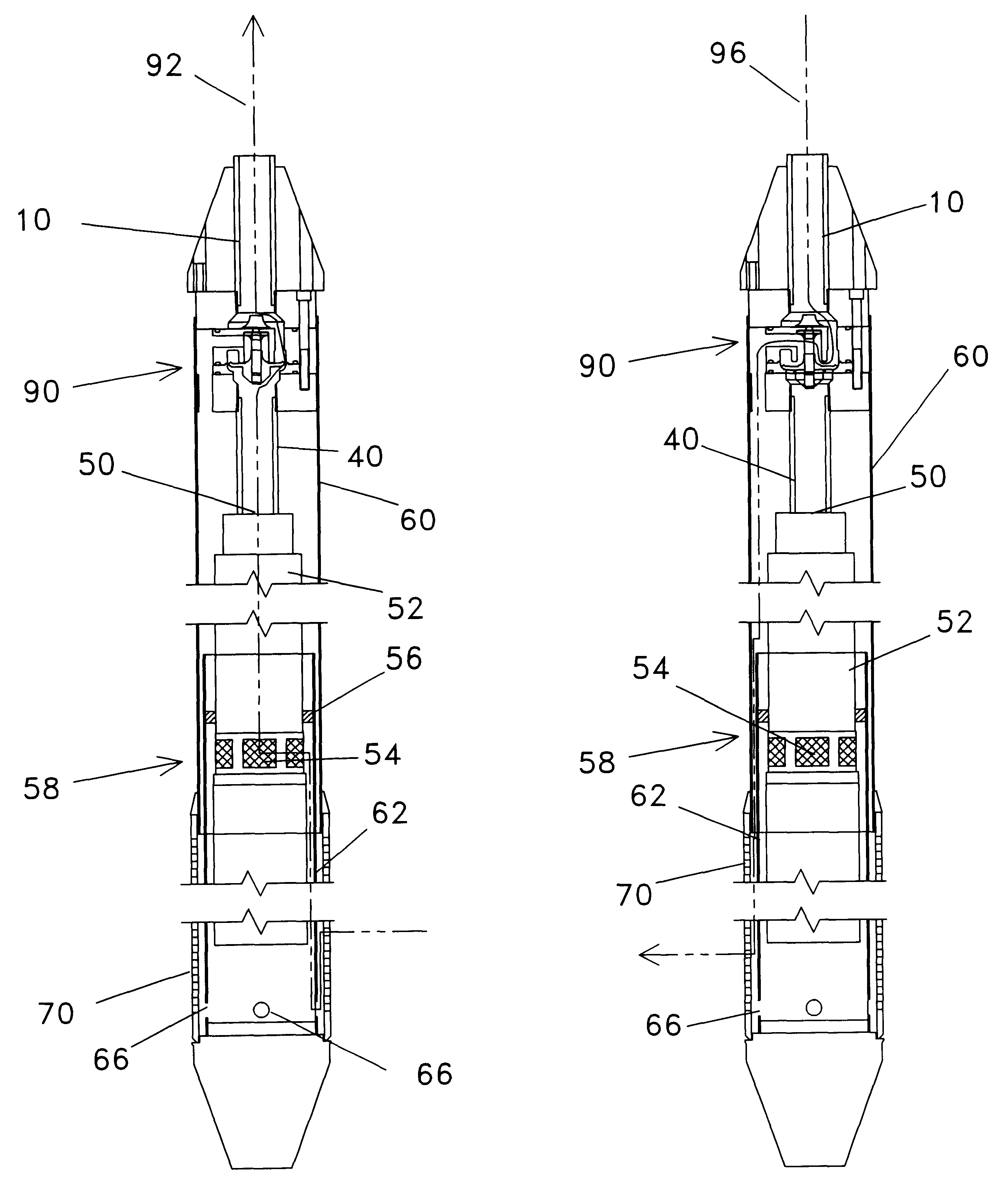
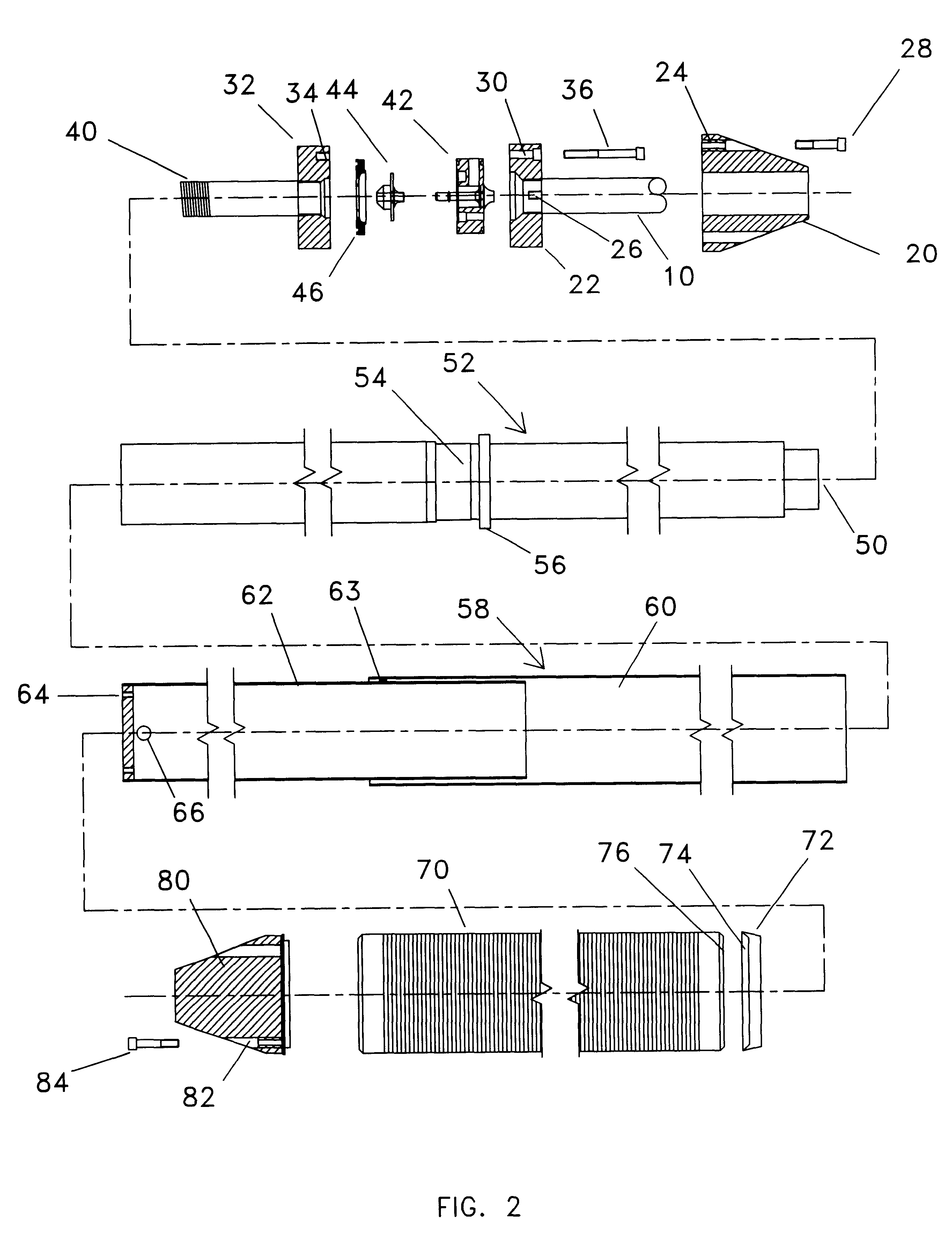
Referring to the drawings, FIGS. 1 through 5B and 7, there is shown a preferred form of the pump protection system embodying the present invention. The pump protection system of the instant invention may be used to prevent clogging, promote cooling, and self-clean any pumping system in which the pumping system includes a pump intake port which is susceptible to being clogged by unwanted solid particles.

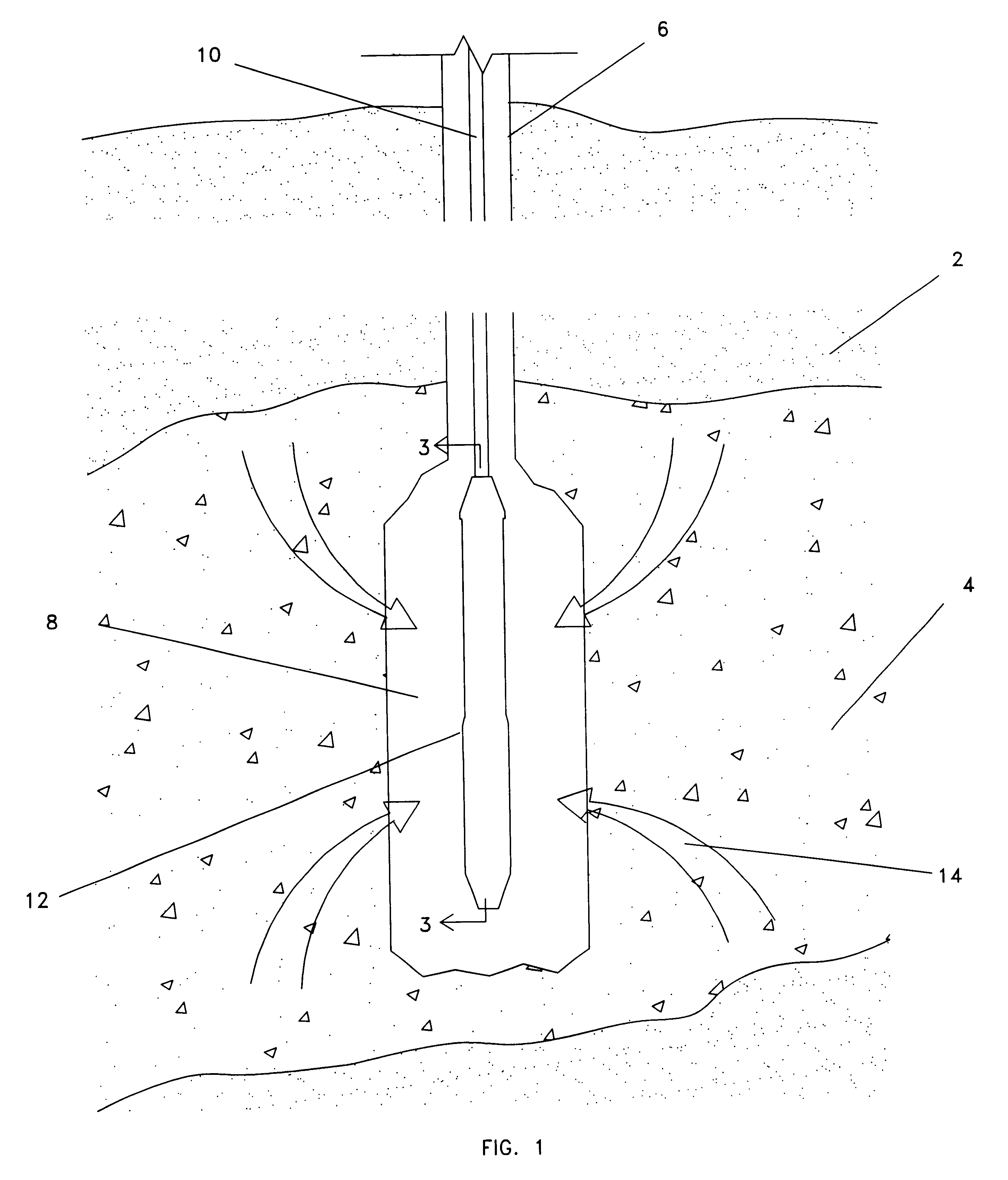
Referring to FIG. 1, a side view of a well pumping system including the pump protection system of the instant invention is shown. Although the pump protection system could be used in a variety of situations, the system depicted in FIG. 1 will be used for a description of a preferred embodiment of the instant invention. Area 2 depicts any type of underground composition. Coal seam 4 depicts a coal seam within area 2 which is porous and permeable and contains water and methane. Well casing 6 is an enclosed section (usually by some type of pipe) which runs from the surface to the coal se...


PUM


Abstract

Embodiments of a pump protection system are disclosed which may be used to enclose, protect, and improve the efficiency of a submersible pump. The pump protection system of the instant invention prevents unwanted materials from clogging the pump intake port and from entering the pump intake port to damage the internal parts of the pump. The pump protection system may be back flushed to clean the pump protection system without damaging the pump. The pump protection system also prevents entrained gasses from entering the pump. A pressure relief valve is also disclosed which provides back pressure on the pump at pump startup.

Description

1. Field of the InventionThe present invention relates generally to pumping of natural resources from below ground to the surface and more specifically to devices to protect and improve the efficiency of pumps used for such purposes.2. Background InformationIn the United States and throughout the world, a variety of natural resources including oil, water, and methane (a natural gas), are found beneath the earth's surface and brought to the surface through a variety of wells. In some instances these resources are under pressure and will naturally flow through the well to the surface without application of other means. In other cases, a pump which has much of its components on the surface is used to pump the resource from the ground. In some instances, a pump, often a submersible pump, is placed beneath the surface in a production zone within or near the source of the resource.In most cases in which an underground pump is used, a hole is drilled from the surface to the production zone...

Claims


Application Information

Patent Timeline
Patent Type & Authority Patents(United States)
IPC IPC(8): E21B43/12
CPCE21B43/121
Inventor SKILLMAN, DALE
Owner SKILLMAN DALE
Why Eureka
Try Eureka